Racking-lock bracket—initial tasks – GE Industrial Solutions EntelliGuard R AKD-5 User Manual
Page 20
19
EntelliGuard R Circuit Breaker Retrofill AKD-5 Installation Manual DEH-41547 02/12
9. Place the cassette on a work table.
The cassette should be positioned such that there is enough overhang of its side so that you can
insert the position switch actuator assembly in the bottom of the cassette. Alternately, the
installation can also be done by placing the cassette assembly on the retrofit AK50 while it is on
the telescopic rails of the AKD5 compartment, being retrofitted.
10. As soon as the position switch actuator is installed, slide the assembly up from the bottom of the
cassette. When inserted, flip the position switch.
11. Line up the holes on the cassette side sheet with the holes provided on the actuator assembly.
12. Fasten the 3 M6 bolts and 6mm washers provided with the actuator assembly to the three holes
on the cassette side sheet. Two holes are placed on the side and one hole on the rear of the
cassette assembly.
The position switch actuator on the cassette is now installed and ready to be activated as soon as
the breaker is racked into the compartment.
13. Mount the cassette assembly on the rails of the AK25 cabinet in the AKD-5 and rack the cassette
into the compartment of the AKD-5 LVS.
Note: As the EntelliGuard ACB breaker is racked in the cassette, the position indicator window reads
“connected”. This indicates that the retrofit system has activated the position switch in the LVS.
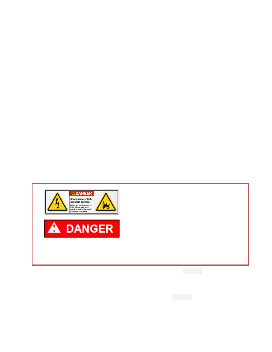
Racking-Lock Bracket—Initial Tasks
• It must be ensured that the supply power
to the compartment is turned off/
compartment is de-energized for all the
incoming and outgoing circuits of the LVS
prior to any work being conducted on it.
•
During the installation and related work on
the equipment, it must be ensured that the
operator is using the prescribed PPE for the
specified tasks.
• Ensure only qualified personnel install, operate, service, and maintain all electrical
equipment.
1. Remove existing indicator assembly system from AKD-5 cabinet rails (
Figure 13
).
2. Clean the area of the moving frame assembly of any dirt or debris.
3. Unpack the racking lock kit for the AKD-5.
4. Use this bracket as a template for drilling the holes in the frame (
Figure 14
).