Installing spectra series™ busway – GE Industrial Solutions Spectra II Series Plug-in and Feeder Busway with BlueCoat Epoxy Insulation System User Manual
Page 5
Spectra and Spectra II Series™ Plug-In and Feeder Busway
Installing Spectra Series Busway
3
Installing Spectra Series™ Busway
Storage Precautions
Before storing, unpack sufficiently to make a
check of the busway for possible concealed
damage resulting from shipping and handling. If
damage has occurred, notify the shipper
immediately. If the busway is free of damage,
restore the packing until ready for installation.
Store indoors in a clean, dry area, preferably close
to the installation points.
Protect the busway from mechanical damage and
any contact with or exposure to corrosive fumes,
liquids, salts, or concrete.
Failure to store and protect the busway properly
can cause serious damage and will void the
warranty.
NOTE: No busway, including outdoor rated, is
weatherproof until completely and properly
installed.
NOTE: Aucune canalisation pour barres omnibus,
incluant celles classées pour l'extérieur, n'est à
l'épreuve de l'eau jusqu'à ce qu'elle soit installée
complètement et correctement.
Pre-Installation Procedure
When possible, deliver the busway to its
installation location before unpacking. Large
labels on each shipping carton or crate designate
the items contained. Additionally, each busway
piece is identified with an item number label.
Inspect each busway piece for possible damage
or contamination. Contact surfaces must be clean.
However, do not attempt to polish tarnished
contact surfaces.
Check to ensure that joint insulators are not
damaged or cracked and are firmly in place.
Megohm test each piece before installation.
Installation of Spectra Series Busway
Establish the bus bar phase sequence (Ø side is
labeled) to determine how the busway is to be
installed, so that correct phasing is maintained
throughout the system. Note that phase
transposition lengths, when furnished, may
relocate the Ø to the opposite side of a busway
run.
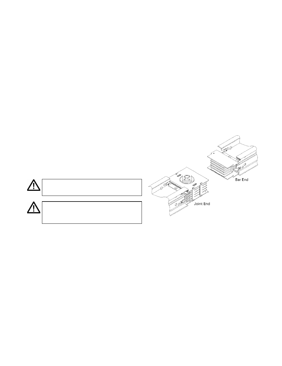
Each busway piece has a ―bar end‖ and a ―joint
end,‖ as illustrated in Figure 1. Normally the
busway is oriented end for end with bar ends
pointing away from the source. Also, the ø side
should be oriented down for horizontal plug-in
applications.
Figure 1. The bar end and joint end of the busway.
In vertical riser installations, it is easier to lower
the busway into place than it is to raise it.
If installation drawings have been furnished,
information regarding the orientation of the
busway and location of the ø side, as well as other
pertinent data, will be furnished. These drawings
should be followed carefully to ensure a proper
busway system.
Where to Start
Start the installation, if at all possible, at the most
critical point, such as a main feed box,
switchboard or switchgear, elbow, or other critical
fitting or termination.