GE Industrial Solutions Spectra II Series Plug-in and Feeder Busway with BlueCoat Epoxy Insulation System User Manual
Page 14
Spectra and Spectra II Series™ Plug-In and Feeder Busway
Installing and Removing Spectra Busway Plugs
12
AVERTISSEMENT: DANGER DE CHOC ÉLECTRIQUE
OU DE BRÛLURE! La fiche-boîtier doit être à OFF
avant de l'installer ou de la retirer de la barre
blindée. Le non-respect de cette directive
pourrait causer une blessure sérieuse ou la mort!
C'est une pratique sécuritaire de mettre hors
tension la barre blindée avant d'insérer ou de
retirer les fiches-boîtiers de barre omnibus. Il est
nécessaire aux États-Unis de respecter toutes les
procédures de sécurité tant fédérales que locales
y compris le NFPA 70E 2-1.3 réglementant
l'utilisation d'équipement de protection individuel
(ÉPI) tel qu'écran facial, gants isolants et
vêtements ignifuges. Au Canada, assurez-vous
d'observer les exigences appropriées du Code
électrique canadien. Seul un personnel
correctement entraîné peut installer des fiches-
boîtiers ou les retirer d'une barre blindée
alimentée. De plus, toutes les instructions quant à
l'installation de fiches-boîtiers de barre omnibus
doivent être suivies entièrement.
Note the following points concerning busway
plugs:
Inspect the plug before installing on the
busway.
Stab fingers have been lubricated with grease,
which should not be removed.
Busway plug-in outlets are made accessible
by hinging the outlet cover 180°. A high-
friction hinge holds the cover open.
An alignment pin polarizes and locates the
plug in the correct position only.
CAUTION: Do not rest the weight of the bus plug
on the alignment pin during installation. The pin
must be used for alignment only. The plug must
be adequately supported by independent means
until all the hanger bolts are tightened.
ATTENTION: Le poids de la fiche-boîtier de barre
omnibus ne doit pas reposer sur la tige
d'alignement durant l'installation. La tige doit être
utilisée uniquement pour l'alignement. La fiche-
boîtier doit être soutenue adéquatement par des
moyens indépendants jusqu'à ce que les
boulons-vis soient serrés.
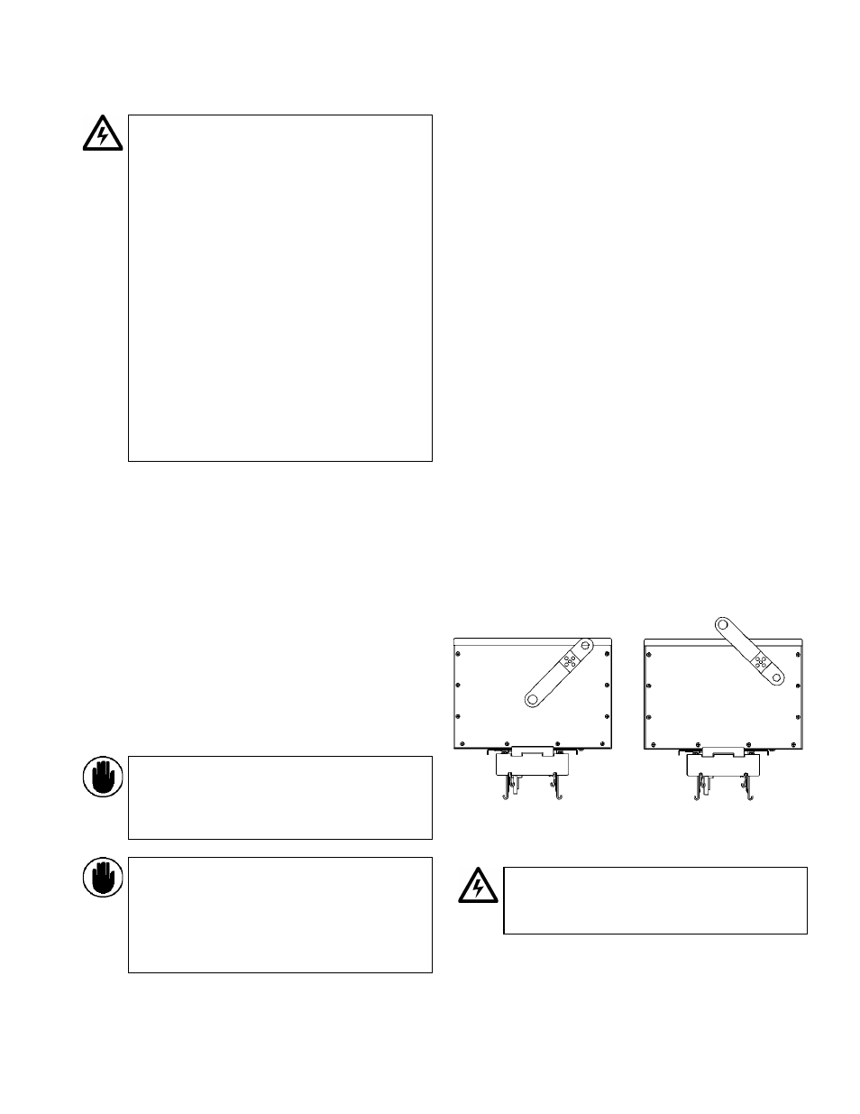
The plug handle is originally in the shipping
position. Remove the center screw and rotate
the handle 90
CW to access the lock-out
feature. Reinsert the screw to secure the
handle. NEC requires the ON handle position to
be up and the OFF handle position to be down,
as shown in Figure 17.
Plugs are interlocked, permitting engagement
and disengagement with the busway only
when in the OFF position.
Place the operating handle at the desired
position on the plug and secure it with the
screw provided. The NEC requires the ON
handle position to be up and the OFF handle
position to be down.
If plug-assist has been furnished on the plug,
the operating handle may be used as a
wrench to operate the mechanism.
To install a plug where the rear plug hanger
interferes with a joint cap, it is necessary to
remove the break-off tabs, as shown in Figure
18.
See the note below Figure 18 concerning the
hanger hooks kit.
On large plugs, drop rod brackets are provided
for auxiliary support of the plug on horizontal
runs.
Figure 17. Plug handle position.
WARNING: Perform all of the following steps to
insure proper plug-to-bus engagement. Failure to
do so may cause injury, death, or damage to
equipment.
Shipping Position
Operating Position