GE Industrial Solutions Spectra II Series Plug-in and Feeder Busway with BlueCoat Epoxy Insulation System User Manual
Page 12
Spectra and Spectra II Series™ Plug-In and Feeder Busway
Installing and Removing Spectra Busway Plugs
10
torque-indicating bolt is used, tighten using a
3/4‖ or 19-mm socket torque wrench set at
50ft-lb (68N-m). The color indicator should turn
fully black and can be viewed periodically to
insure proper torque.
NOTE: The bolt head may be relocated to the
opposite side of the busway to improve
accessibility.
NOTE: La tête du boulon peut être repositionnée
sur le côté opposé de la canalisation pour barres
omnibus pour la rendre plus accessible.
13. Tighten all 3/8" joint cap screws to 25 lb-ft (34
N-m) with a 9/16" or 14-mm socket wrench
and all 5/16" joint cap screws to 10 lb-ft (14 N-
m) with a 1/2" or 12-mm socket wrench.
14. During installation, occasionally megohm test
the assembly to check for any improperly
made joints. Resistance should not drop below
1 megohm per 100 feet of busway.
15. Megohm test the complete run before
energizing.
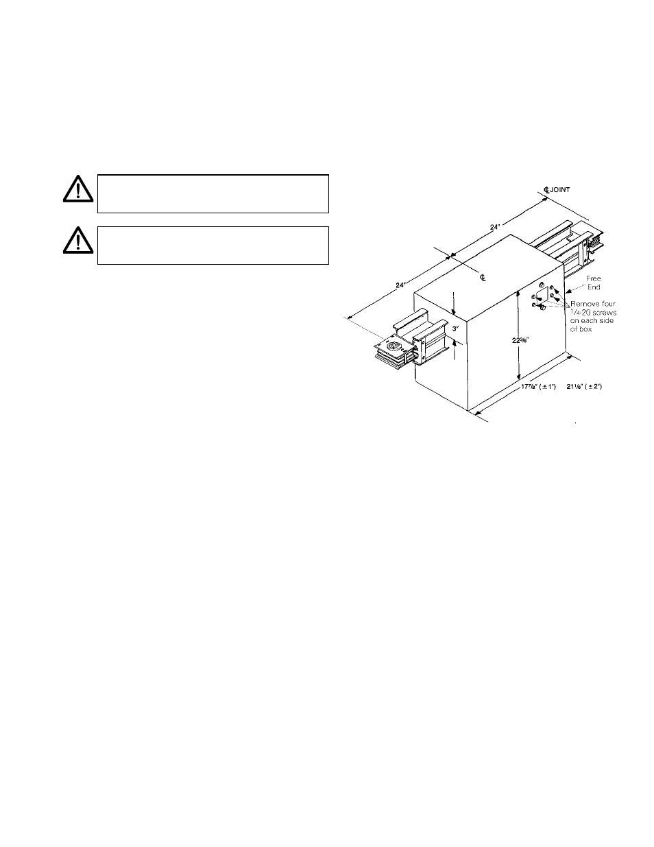
Expansion Lengths
Expansion lengths compensate for thermal
expansion of a long busway run or for differential
expansion between two buildings spanned by a
busway run. One end wall of the expansion box is
free to move, but only after the eight 1/4-20
shipping screws are removed.
Install the expansion length and the remaining
busway run, as shown in Figure 14. All but the
farthest busway supports beyond the box’s free
end must be nonrigid, such as spring hangers for
riser (vertical) busway or drop rod assemblies on a
horizontal run. Before energizing the run, remove
the eight 1/4-20 shipping screws, four on each
side of the box, as identified by two labels.
Tips for installing expansion lengths
The label and shipping screws are near the
box’s free end.
Use a 3/8" (6- or 12-point) or 10-mm (6-point)
socket wrench to remove the 1/4-20 shipping
screws.
An elbow below a riser that is supported by a
drop rod less than 8 feet from the elbow
should be considered rigidly mounted.
Figure 14. Installing an expansion length.
Busway Field Check Pieces and Replacement
Pieces
A field check piece is a length of busway inserted
into a run after the major portion of that run has
been installed. To determine the length of the
piece to be inserted, measure the opening length
L between the ends of the bars and the center of
the joint of the adjacent piece and subtract .875
inches, as shown in Figure 15. This is equal to the
busway length X measured from the center lines
of joint to joint and is the way to measure all
Spectra Series busway pieces.