GE Industrial Solutions Spectra II Series Plug-in and Feeder Busway with BlueCoat Epoxy Insulation System User Manual
Page 26
Spectra and Spectra II Series™ Plug-In and Feeder Busway
Installing Spectra II Series Busway
24
3. Align sections to be joined by matching up
―Ø side‖ labels attached at ends of each
section.
4. If necessary, loosen joint bolt slightly.
5. Slide sections together. Make sure that the
busbars interweave the insulators as shown
in Figure 36-38. NOTE: the housing ground
side plates must pass between the outside
insulators and the joint sides.
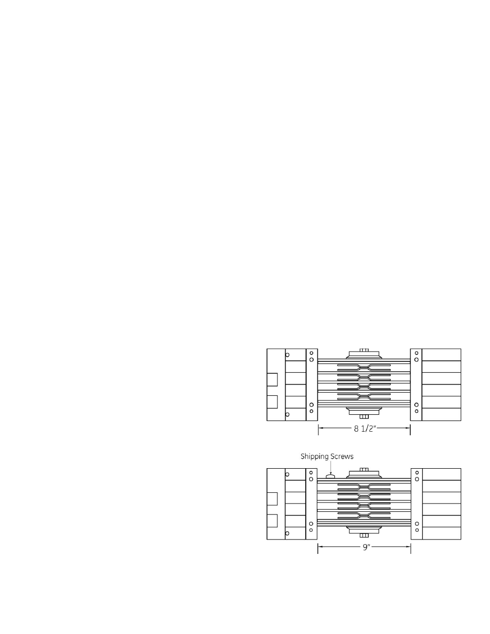
6. The standard distance between the
housings is 9‖ as shown in Figure 37.
However, the joint is also adjustable as
shown in Figures 36-38. Simply move the
sections in or out to the desired length as
shown and remove the twist outs in both
joint caps. See Figure 39 NOTE: Remove
shipping screw to center joint when
adjusting to max. and min. length.
7. Insert mounting screws into the joint cap
which is already attached and tighten to
align centerlines of the two bus sections.
8. Inspect busway run for the straightness in
all planes, and make adjustments, if
necessary, for good alignment.
9. Lubrication grease has been applied to the
joint bolt head and thread to reduce friction.
Do not remove this grease.
10. Tighten the joint bolt to 50 foot-pounds.
When the Belleville springs on both sides are
flattened, the bolt is fully torqued. The bolt
head may be relocated to the opposite side
of the busway if it is inaccessible.
11. Install second joint cap and tighten the joint
cap screws.
12. During installation occasional meggering
should reveal any improperly made
assemblies. Resistance should not drop
below one megohm for 100 feet of busway.
Megger the complete run before energizing.
To Remove the Joint or Captive Piece of
Busway
Should it become necessary to isolate for
testing or troubleshooting a piece or run off
Spectra and Spectra II Series ™ busway the
joint is designed for easy removal either during
or after installation.
1. De-energize the busway. Remove either
joint cap.
2. Remove the shipping screw, illustrated in
Figure 37.
3. Grasp the joint sides and pull toward the
narrow side of the busway. A gently rocking
motion may necessary to aid the joint in
sliding out.
NOTE: With the joint removed the busway is
segmented and section of the run away
from the source is electrically isolated from
the source.
4. To reinstall the joint, simply slide the joint
back into place. CARE MUST BE TAKEN TO
ASSURE SPLICE PLATES AND INSULATORS
ARE PROPERLY POSITIONED. It is not
necessary to reinstall the shipping screw.
5. Install joint cap(s), as required.
6. Megger at 1000VDC the complete run of
busway before energizing.
Joints With +/- .50 Inch Adjustability
Figure 36 “Minimum”
Figure 37 “Standard”