Stud shield modification, Remounting primary disconnects, Modification of the lower stud shields – GE Industrial Solutions ProTrip Conversion Kits AK-15, AK-25, and AKU-25 User Manual
Page 15: Primary disconnect modification for ak-15 breakers
15
Stud Shield Modification
Modify the left- and right-pole lower stud insulator shields
as illustrated in Figure 24. Remount on the back plate
using the original screws and special nuts supplied with
the kit.
Remounting Primary Disconnects
On draw-out breakers, remount the primary disconnect
fingers to the new lower studs.
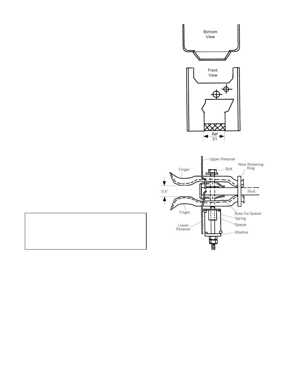
On AK-15 breakers only, use the following procedure to
modify the primary disconnects, as illustrated in Figure
25.
1. Place the spacer with the off-center hole in the hole
in the stud, while sliding the new retainer completely
over the stud.
2. Place the new retaining ring on the stud. Insert the tip
of the upper fingers under the retaining ring and
place the bow-tie spacers in the fingers.
3. Place the retainer over the upper fingers and insert
the bolt.
4. Inset the tip of the lower fingers under the retaining
ring and place the bow-tie spacers in the fingers.
Locate the lower retainer to hold the bow-tie spacers
in place.
5. Place the cylindrical spacer and spring on the bolt
and secure it with a washer and nut.
6. Tighten the nut to obtain 60–70 pounds of pressure
per set of four fingers when the fingers are spread
1
/
2
inch apart. If a pressure gauge is not available,
compress the spring to
13
/
16
inch to obtain proper
pressure.
CAUTION: Adequate primary contact force is essential.
Tighten the nuts on the
1
/
4
× 20 mounting bolts to obtain
a spring dimension of
13
/
16
to
27
/
32
inch. The proper
distance between the contact fingers is
7
/
16
inch. Proper
contact force is 60–70 pounds, with the contacts spread
to
1
/
2
inch.
Figure 24 Modification of the lower stud shields.
Figure 25. Primary disconnect modification for AK-15
breakers.