Current sensor installation, Current sensor assembly, right-side view, Ct terminal board bracket and insulator installed – GE Industrial Solutions ProTrip Conversion Kits AK-15, AK-25, and AKU-25 User Manual
Page 13: Completed, Ct installation
13
SECTION 4. BACK-FRAME
CONVERSION
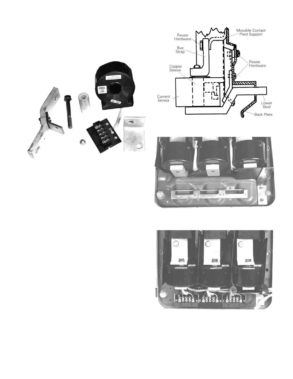
The components used in the installation of the current
sensor for each pole are shown in Figure 19.
Figure 20. Current sensor assembly, right-side view.
Figure 19. Components for the current sensor assembly
for one pole.
Current Sensor Installation
The three current sensors (CTs) are mounted to the back
frame in the locations from which the existing trip devices
were removed. The following installation process is
illustrated in Figure 20.
1. Insert the lower copper stud through the rectangular
slot in the back frame and attach it with the existing
mounting screw.
Figure 21. CT terminal board bracket and insulator
installed..
2. Place the right-angle bus strap in position in the back
frame and loosely attach it with the existing bolt.
3. Insert the copper sleeve into the center of the CT,
then place the CT in position between the bus strap
and lower stud. Loosely secure it with the long bolt
through the bus strap and CT into the tapped hole in
the stud.
4. Align the assembly, then tighten the two
3
/
8
-inch
bolts in the bus strap to 250 in-lb to assure proper
contact integrity.
5. Install the CT terminal board-mounting bracket below
the CTs with the two #8-32
×
1
/
2
-inch screws
provided, as shown in Figure 21. Bring the screws in
from the rear through the existing holes in the back
frame.
Figure 22. Completed CT installation..
6. Install the insulator and bracket to the right side of
the back frame below the CTs with the screws and
nuts provided, as shown in Figure 21.
7. Mount the terminal boards from each CT to the
bracket with the six #6-32
×
1
/
2
-inch screws and
washers provided, as shown in Figure 22.