Data sheet, Thermal considerations, Through-hole soldering information – GE Industrial Solutions EVK011A0B Series (Eighth-Brick) User Manual
Page 9
GE
Data Sheet
EVK011A0B Series (Eighth-Brick) DC-DC Converter Power Modules
36–60Vdc Input; 12.0Vdc Output; 11A Output Current
May 15, 2013
©2012 General Electric Company. All rights reserved.
Page 9
Thermal Considerations
(continued)
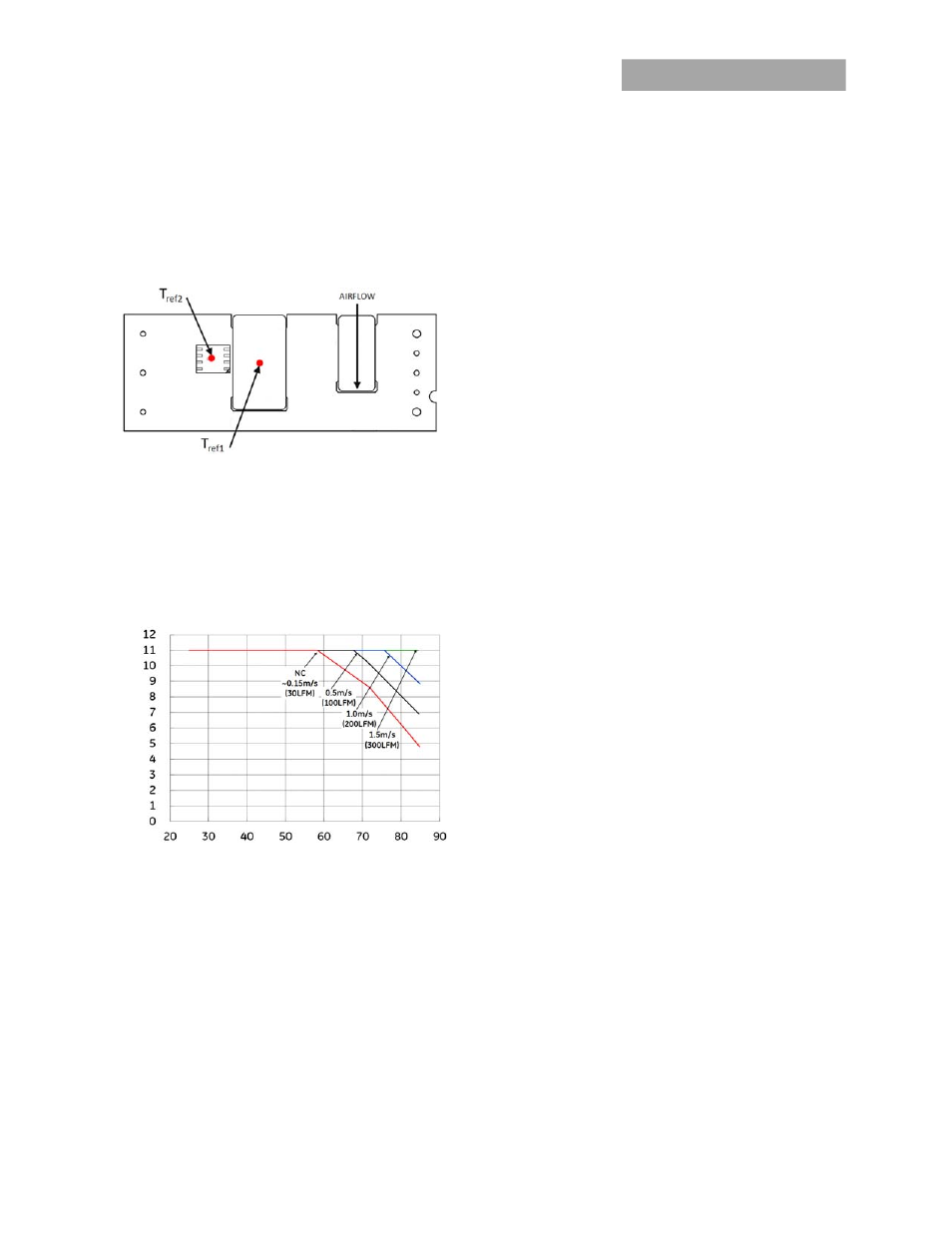
Heat-dissipating components are mounted on the top side
The thermal reference points, T
ref1
and T
ref2
used in the
specifications for open frame modules is shown in Figure 13.
For reliable operation T
ref1
should not exceed 128
o
C, and T
ref2
should not exceed 123
o
C .
Figure 13. T
ref
Temperature Measurement Location for open
Frame Module.
Heat Transfer via Convection
Increased airflow over the module enhances the heat
transfer via convection. Derating curves showing the
maximum output current that can be delivered by the open
frame module versus local ambient temperature (T
A
) for natural
convection and up to 1.5m/s (300 ft./min) forced airflow are
shown in Figure 14.
OUTPUT C
U
RR
EN
T,
I
O
(A
)
AMBIENT TEMEPERATURE, T
A
(
o
C
)
Figure 14. Output Current Derating for the Open Frame
Module; Airflow in the Transverse Direction from Vout(+) to
Vout(-); Vin =48V.
Please refer to the Application Note “Thermal Characterization
Process For Open-Frame Board-Mounted Power Modules” for a
detailed discussion of thermal aspects including maximum
device temperatures.
Through-Hole Soldering Information
The RoHS-compliant (Z codes) through-hole products use the
SAC (Sn/Ag/Cu) Pb-free solder and RoHS-compliant components.
The RoHS-compliant with lead solder exemption (non-Z codes)
through-hole products use Sn/Pb solder and RoHS-compliant
components. Both non-Z and Z codes are designed to be
processed through single or dual wave soldering machines. The
pins have an RoHS-compliant finish that is compatible with both
Pb and Pb-free wave soldering processes. A maximum
preheat rate of 3C/s is suggested. The wave preheat
process should be such that the temperature of the
power module board is kept below 210C. For Pb solder,
the recommended pot temperature is 260C, while the
Pb-free solder pot is 270C max. Not all RoHS-
compliant through-hole products can be processed with
paste-through-hole Pb or Pb-free reflow process. If
additional information is needed, please consult with
your GE representative for more details.
Post Solder Cleaning and Drying Considerations
Post solder cleaning is usually the final circuit-board
assembly process prior to electrical board testing. The
result of inadequate cleaning and drying can affect both
the reliability of a power module and the testability of
the finished circuit-board assembly. For guidance on
appropriate soldering, cleaning and drying procedures,
refer to GE Board Mounted Power Modules: Soldering
and Cleaning Application Note (AN04-001).