Data sheet, Feature descriptions, Thermal considerations – GE Industrial Solutions EVK011A0B Series (Eighth-Brick) User Manual
Page 8
GE
Data Sheet
EVK011A0B Series (Eighth-Brick) DC-DC Converter Power Modules
36–60Vdc Input; 12.0Vdc Output; 11A Output Current
May 15, 2013
©2012 General Electric Company. All rights reserved.
Page 8
Feature Descriptions
(continued)
Output Voltage Programming
Trimming allows the output voltage set point to be increased or
decreased, this is accomplished by connecting an external
resistor between the TRIM pin and either the V
O
(+) pin or the V
O
(-)
pin.
V
O
(+)
V
O
TRIM
V
O
(-)
R
trim-down
LOAD
V
IN
(+)
ON/OFF
V
IN
(-)
R
trim-up
Figure 12. Circuit Configuration to Trim Output Voltage.
Connecting an external resistor (R
trim-down
) between the TRIM pin
and the Vo(-) (or Sense(-)) pin decreases the output voltage set
point. To maintain set point accuracy, the trim resistor tolerance
should be ±1.0%.
The following equation determines the required external resistor
value to obtain a percentage output voltage change of ∆%
k
R
down
trim
22
.
10
%
511
Where
100
%
,
,
set
o
desired
set
o
V
V
V
For example, to trim-down the output voltage of the module by
8% to 11.04V, Rtrim-down is calculated as follows:
8
%
k
R
down
trim
22
.
10
8
511
655
.
53
down
trim
R
Connecting an external resistor (R
trim-up
) between the TRIM pin
and the V
O
(+) (or Sense (+)) pin increases the output voltage set
point. The following equations determine the required external
resistor value to obtain a percentage output voltage change of
∆%:
k
V
R
set
o
up
trim
22
.
10
%
511
%
225
.
1
%)
100
(
11
.
5
,
Where
100
%
,
,
set
o
set
o
desired
V
V
V
For example, to trim-up the output voltage of the module by 5%
to 12.6V, R
trim-up
is calculated is as follows:
5
%
k
R
up
trim
22
.
10
5
511
5
225
.
1
)
5
100
(
0
.
12
11
.
5
k
R
up
trim
8
.
938
The voltage between the Vo(+) and Vo(–) terminals must
not exceed the minimum output overvoltage protection
value shown in the Feature Specifications table. This
limit includes any increase in voltage due to remote-
sense compensation and output voltage set-point
adjustment trim.
Although the output voltage can be increased by both
the remote sense and by the trim, the maximum
increase for the output voltage is not the sum of both.
The maximum increase is the larger of either the remote
sense or the trim. The amount of power delivered by the
module is defined as the voltage at the output terminals
multiplied by the output current. When using remote
sense and trim, the output voltage of the module can be
increased, which at the same output current would
increase the power output of the module. Care should
be taken to ensure that the maximum output power of
the module remains at or below the maximum rated
power (Maximum rated power = V
O,set
x I
O,max
).
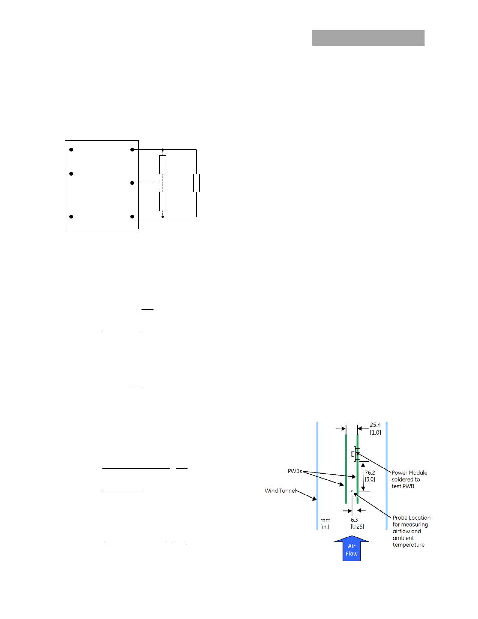
Thermal Considerations
The power modules operate in a variety of thermal
environments; however, sufficient cooling should be
provided to help ensure reliable operation.
Considerations include ambient temperature, airflow,
module power dissipation, and the need for increased
reliability. A reduction in the operating temperature of
the module will result in an increase in reliability. The
thermal data presented here is based on physical
measurements taken in a wind tunnel, using automated
thermo-couple instrumentation to monitor key
component temperatures: FETs, diodes, control ICs,
magnetic cores, ceramic capacitors, opto-isolators, and
module pwb conductors, while controlling the ambient
airflow rate and temperature. For a given airflow and
ambient temperature, the module output power is
increased, until one (or more) of the components
reaches its maximum derated operating temperature,
as defined in IPC-9592. This procedure is then repeated
for a different airflow or ambient temperature until a
family of module output derating curves is obtained.