Picotlynx, 3a: non-isolated dc-dc power modules, Data sheet – GE Industrial Solutions PicoTLynx 3A User Manual
Page 13: Ω − = k vo rtrim 6 . 0 2 . 1
GE
Data Sheet
PicoTLynx
TM
3A: Non-Isolated DC-DC Power Modules
2.4Vdc –5.5Vdc input; 0.6Vdc to 3.63Vdc output; 3A Output Current
September 11, 2013
©2013 General Electric Company. All rights reserved.
Page 13
Figure 38. Circuit configuration for using positive On/Off
logic.
For negative logic On/Off modules, the circuit configuration is
shown in Fig. 39. The On/Off pin should be pulled high with
an external pull-up resistor (suggested value for the 2.4V to
5.5Vin range is 3.6Kohms). When transistor Q1 is in the OFF
state, the On/Off pin is pulled high and the module is OFF.
The On/Off threshold for logic High on the On/Off pin
depends on the input voltage and its minimum value is V
IN
–
1.6V. To turn the module ON, Q1 is turned ON pulling the
On/Off pin low.
100K
Q1
GND
PWM Enable
ON/OFF
VIN+
ON/OFF
_
+
V
I
MODULE
Rpullup
ON/OFF
2.05K
20K
Figure 39. Circuit configuration for using negative On/Off
logic.
Overcurrent Protection
To provide protection in a fault (output overload) condition,
the unit is equipped with internal current-limiting circuitry
and can endure current limiting continuously. At the point of
current-limit inception, the unit enters hiccup mode. The unit
operates normally once the output current is brought back
into its specified range.
Overtemperature Protection
To provide protection in a fault condition, the unit is equipped
with a thermal shutdown circuit. The unit will shutdown if the
overtemperature threshold of 140
o
C is exceeded at the
thermal reference point T
ref
. The thermal shutdown is not
intended as a guarantee that the unit will survive
temperatures beyond its rating. Once the unit goes into
thermal shutdown it will then wait to cool before attempting to
restart.
Input Undervoltage Lockout
At input voltages below the input undervoltage lockout limit,
the module operation is disabled. The module will begin to
operate at an input voltage above the undervoltage lockout
turn-on threshold.
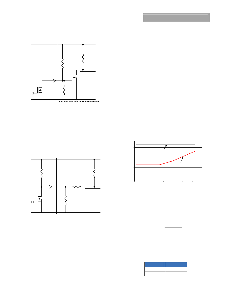
Output Voltage Programming
The output voltage of the Pico TLynx
TM
3A modules can be
programmed to any voltage from 0.6Vdc to 3.63Vdc by
connecting a resistor between the Trim and GND pins of the
module. Certain restrictions apply on the output voltage set
point depending on the input voltage. These are shown in the
Output Voltage vs. Input Voltage Set Point Area plot in Fig. 40.
The Upper Limit curve shows that the entire output voltage
range is available with the maximum input voltage of 5.5V. The
Lower Limit curve shows that for output voltages of 1.8V and
higher, the input voltage needs to be larger than the minimum
of 2.4V.
0
1
2
3
4
5
6
0.5
1
1.5
2
2.5
3
3.5
4
Output Voltage (V)
In
p
u
t V
o
lt
ag
e (
v)
Upper Limit
Lower Limit
Figure 40. Output Voltage vs. Input Voltage Set Point Area
plot showing limits where the output voltage can be set for
different input voltages.
Without an external resistor between Trim and GND pins, the
output of the module will be 0.6Vdc. To calculate the value of
the trim resistor, Rtrim for a desired output voltage, use the
following equation:
(
)
Ω
−
=
k
Vo
Rtrim
6
.
0
2
.
1
Rtrim is the external resistor in kΩ
Vo is the desired output voltage.
Table 1 provides Rtrim values required for some common
output voltages.
Table 1
V
O, set
(V)
Rtrim (KΩ)
0.6 Open
1.0 3.0
100K
Q1
GND
PWM Enable
ON/OFF
VIN+
ON/OFF
_
+
I
V
MODULE
ON/OFF
20K
Q2
20K