Thermal considerations, Heat transfer via conduction or convection – GE Industrial Solutions EVW020A0S6R0 Series (Eighth-Brick) User Manual
Page 9
Data Sheet
March 3, 2011
EVW020A0S6R0 Series Eighth-Brick Power Modules
36–75Vdc Input; 6.0Vdc Output; 20A Output Current
LINEAGE
POWER
9
Thermal Considerations
The power modules operate in a variety of thermal
environments; however, sufficient cooling should be
provided to help ensure reliable operation.
Considerations include ambient temperature, airflow,
module power dissipation, and the need for increased
reliability. A reduction in the operating temperature of
the module will result in an increase in reliability. The
thermal data presented here is based on physical
measurements taken in a wind tunnel.
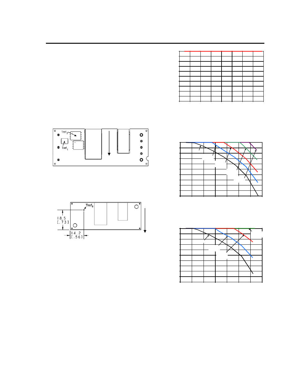
The thermal reference points, Tref
1
and Tref
2
used in
the specifications for open frame modules are shown
in Figure 13. For reliable operation Tref
1
should not
exceed 122
O
C and Tref
2
should not exceed 124
O
C
Figure 13. T
ref
Temperature Measurement
Location for Open Frame Module.
The thermal reference point, Tref
3
used in the
specifications for modules with heatplate is shown in
Figure 14. For reliable operation this temperature
should not exceed 105
O
C.
Figure 14. T
ref
Temperature Measurement
Location for Module with Heatplate.
Heat Transfer via Conduction or Convection
Thermal derating is presented for two different
applications: 1) Figure 15, the EVW020A0S6R0
module is thermally coupled to a cold plate inside a
sealed clamshell chassis, without any internal air
circulation; and 2) Figures 16-20, the
EVW020A0S6R0 module is mounted in a traditional
open chassis or cards with forced air flow. In
application 1, the module is cooled entirely by
conduction of heat from the module primarily through
the top surface to a cold plate, with some conduction
through the module’s pins to the power layers in the
system board. For application 2, the module is cooled
by heat removal into a forced airflow that passes
through the interior of the module and over the top
base plate and/or attached heat sink.
OUT
P
UT
C
URR
E
N
T, I
O
(A
)
0
2
4
6
8
10
12
14
16
18
20
20
30
40
50
60
70
80
90
100
COLD PLATE TEMPERATURE, T
C
(
o
C
)
Figure 15. Output Current Derating for the Module
in Conduction Cooling (cold plate) Applications,
with or without Heatplate; T
a
<70ºC in vicinity of
module interior; V
IN
= 48V.
OUT
P
UT
C
URR
E
N
T, I
O
(A
)
0
2
4
6
8
10
12
14
16
18
20
20
30
40
50
60
70
80
90
0.5 m/s
(100LFM)
NC
1.0 m/s
(200LFM)
2.0 m/s
(400LFM)
3.0 m/s
(600LFM)
AMBIENT TEMEPERATURE, T
A
(
o
C
)
Figure 16. Output Current Derating for the Open
Frame Module; Airflow in the Transverse Direction
from Vout(+) to Vout(-); Vin =48V.
O
U
TPU
T
CU
RRE
NT
, I
O
(A
)
0
2
4
6
8
10
12
14
16
18
20
20
30
40
50
60
70
80
90
0.5 m/s
(100LFM)
NC
1.0 m/s
(200LFM)
2.0 m/s
(400LFM)
AMBIENT TEMEPERATURE, T
A
(
o
C
)
Figure 17. Output Current Derating for the Module
with Heatplate; Airflow in the Transverse Direction
from Vout(+) to Vout(-); Vin =48V.
AIRFLOW
AIRFLOW