Electrical diagram and wiring schematics, Special feature for dock accessibility, Warranty – Buyers 13006039 User Manual
Page 8: Raise the liftgate up all the way, Undo the self locking linkage hinge, Fig. 7
8
13006039INST Rev B
Warranty
Buyers Products Co. warrants all truck/trailer hardware manufactured or distributed by it, to be free from defects in material and
workmanship for a period of one year from date of shipment. Parts must be properly installed and used under normal conditions.
Any product which has been altered, including modification, misuse, accident or lack of maintenance will not be considered under
warranty. Normal wear is excluded. The sole responsibility of Buyers Products Co. under this warranty is limited to repairing or
replacing any part or parts which are returned, prepaid, and are found to be defective by Buyers Products Co. Authorization from
Buyers Products Co. must be obtained before returning any part. No charges for transportation or labor performed on Buyers’ products
will be allowed under this warranty.
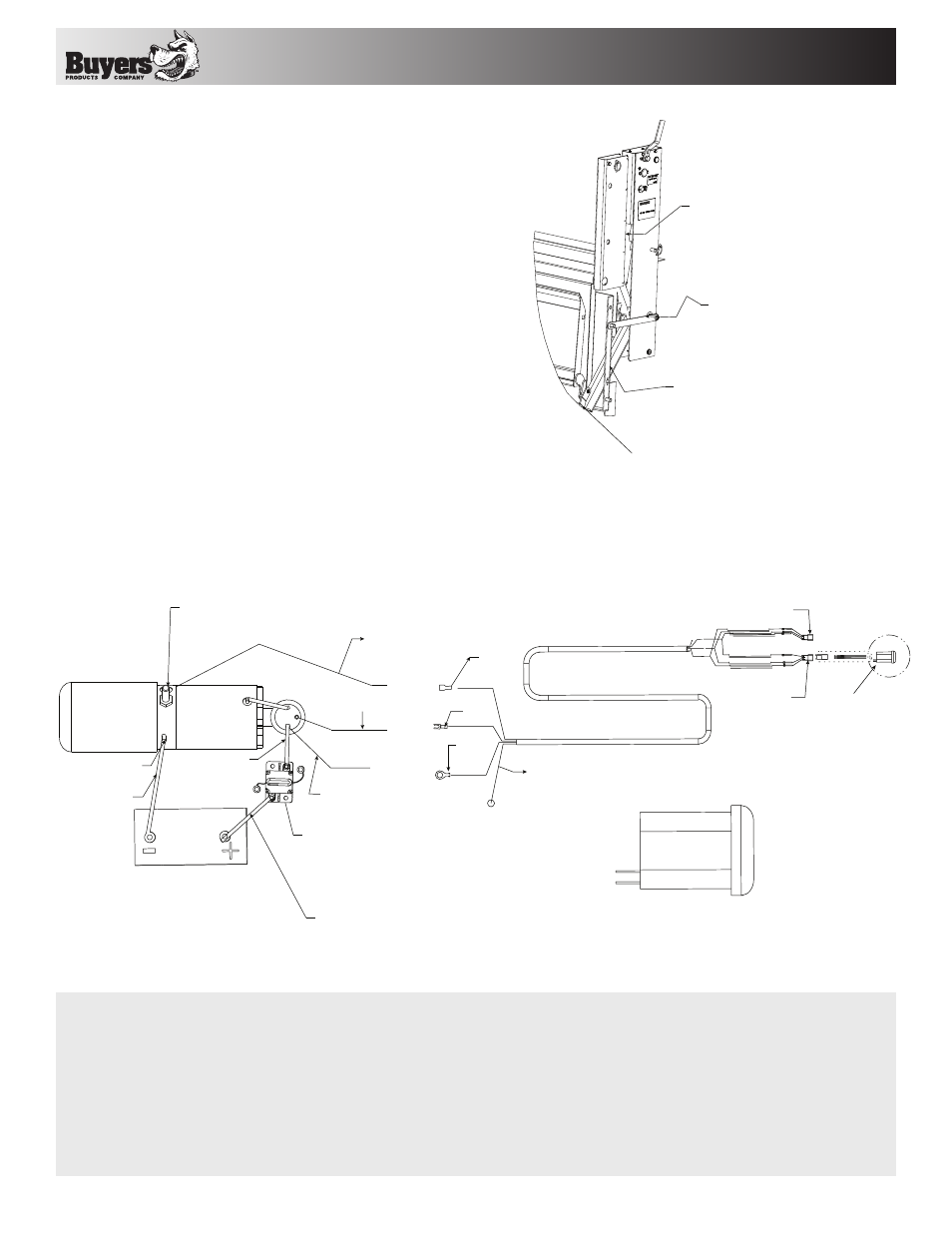
Electrical Diagram and Wiring Schematics
MOUNT HOLE
COMINNG IN
(1) WHITE WIRE --> 1 TERMINAL
(2) BLACK --> 2 TERMINAL
(3) RED --> 3 TERMINAL
JUMPER 1 ---> 8 TERMINAL
LOWERING VALVE WITH
SOLENOID SWITCH
CONNECT TO RED WIRE
TO VALVE SWITCH (3)
PUMP AND MOTOR;
COMMON GROUND
LONG BAT HEAVY
DUTTY CABLE
LONG RED BAT CABLE
CIRCUIT BREAKER WITH
MANUAL RESET OPTION
- MAY HAVE TO DRILL SMALL HOLE
ATTACH TO FIREWALL TRHOUGH
ATTACH THE RING TERMINAL ENDS
TO THIS SOLENOID; WHITE WIRE
ATTACH TO THIS TERMINAL
BLACK WIRE FOR POWERING
MOTOR AND RAISE (2)
RED (3)
BLACK (2)
WHITE (1)
(OPTIONAL WIRE IF NEEDED)
3 WIRE OPTION WILL NOT EXISTED
CUT A SHORT PIECE OF
BAT CABLE TO HAVE
THIS CONNECTION
PLUG FOR USE WITH
REMOTE CONTROL OPTION
CONNECTION FOR
THE KEY SWITCH
SEE DETAIL
A
3.000
SCALE
A
DETAIL
Unless otherwise specified, DO NOT TAMPER with factory setting. Your warranty will be void if not wired accordingly.
Fig. 8.
Special Feature for Dock Accessibility
Your liftgate is accessible to a Dock Access feature
for easy backup.
•
Raise the Liftgate up all the way.
•
Undo the self Locking linkage Hinge
•
Rotate the straight lever into position and lock it
with the Lynch Pin.
•
Push the platform down and hold it into position
while latching the lever into position. Be careful
of the torsion spring pressure.
[4] ROTATE THE
STRAIGHT LEVER
INTO POSITION
- LOCK IT WITH
THE LYNCH PIN
[3] PUSH THE PLATFORM
DOWN AND HOLD IT
INTO POSITION
[1] HAVE THE LIFTGATE
RAISED UP ALL THE WAY
[2] UNDO THE LINKAGE HINGE
LETTING IT HANG FREE
Fig. 7.