Installation instructions (continued) – S&B Filters Cold Air Intake Kit - Cotton Filter 75-5064 User Manual
Page 2
15461 Slover Ave., Fontana, CA 92337 - Phone: (909) 947-0015 - Fax: (909) 947-0603 -
Installation Instructions (continued)
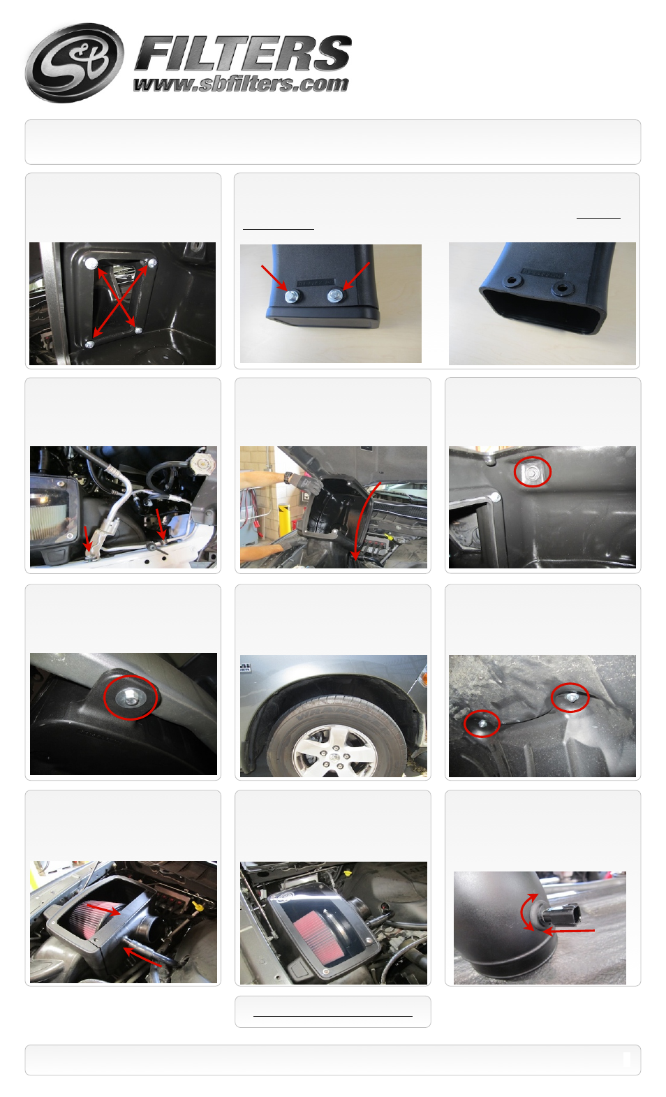
10.
Insert the Air Inlet tube
(S)
onto the Air
Box
(M)
and secure using the supplied
1/4”-20x3/4” screws
(V)
, 1/4” Lock washers
(U)
and 1/4” Flat washers
(W)
.
14.
Using the OE bolt, secure the air box
assembly to the frame. Leave loose for now.
Secure the A/C line assembly if it was
loosened in Step #12.
19.
Install the Clear Lid
(N)
using the supplied
5/16” S.S. Screws
(Q)
and Rubber Washers
(R)
along with the 10-24 Screws
(P)
and SS Sealing
Washers
(O)
. This will secure the Filter Adapter
to the Air Box as well.
(Do not over tighten!)
13.
Carefully install the air box assembly
into the truck at an angle as shown below.
15.
From inside the wheel well, attach the
air box to frame using the supplied M8 x
40mm Hex bolt
(K)
and Fender Washer
(L)
.
Then secure both bolts mounting the air box
to the frame.
16.
Reinstall the wheel liner using 5 of the
OE screws and 3 supplied Panel Pins
(Y)
.
Reinstall wiring harness connector into wheel
liner that was removed in Step #7.
20.
Note the OE Temp. Sensor orientation.
Then carefully pull it out of the OE tube. Insert
the supplied Grommet
(D)
into the Intake
Tube
(E)
. Carefully push the Temp. sensor
into the grommet using a twisting motion. Be
sure to match the OE orientation.
17.
Secure the wheel liner to the air box
using two supplied 1/4”-20x3/4” screws
(V)
and Flat washers
(W)
inside the air box. Use
the 1/4” Nylock nuts
(X)
and 1/4” Flat washers
(W)
under the wheel liner.
SEE EXPLODED VIEW ON PAGE 4
2
P/N: 75-5064 / 75-5064D
18.
Insert the S&B Filter
(J)
onto the Adapter
Tube
(H)
and secure the #104 Hose Clamp
(I)
. Install the assembly into the Air box. Then
push the valve cover breather hose onto the
stem of the Adapter tube.
11.
For those concerned about minimal engine heat; insert the Air Inlet Plug
(T)
into the end of the
Air Inlet tube
(S)
. Attach using the supplied 1/4”-20x3/4” screws
(V)
, 1/4” Lock washers
(U)
and 1/4”
Flat washers
(W)
. For those seeking additional air flow, set the Air Inlet Plug aside and save all the
supplied hardware.
(See page 3 for more info and test results)
12.
On 2013 models; it may be necessary
to shift the A/C line assembly forward to gain
clearance around the Inlet tube. This can be
done loosening the two screws attaching the
assembly to the fender.