4 functional description, 5 factory code example (factory: d2m), 6 description of the control modes – R&M Materials Handling VARIABLE SPEED CONTROLS ControlMaster Select Service Manual User Manual
Page 6: Operation when power is switched on, Normal operation, Other features
R&M Materials Handling, Inc.
4501 Gateway Boulevard
Springfield, Ohio 45502
P.: (937) 328-5100
FAX: (937) 325-5319
6/46
R&M Materials Handling, Inc. reserves the right to alter or amend the above information without notice.
2.4 Functional
description
Operation when power is switched on
-
Stop limit switches S12 & S22 and slow down limit switches S11 & S21 are assumed to be normally closed, as
well as the emergency stop button ES.
-
The control voltage is supplied to X1:5 and X1:6. The main voltage is connected to inverter power supply and
then inverter wakes up.
-
If either of the direction signals S1 or S2 is on, the display shows F6 (fault code, see Chapter ”Inverter fault
codes”) and driving can begin only after the direction signals have been off more than 0.3s.
Normal operation
-
For the description of the speed reference setting see Chapter “Control methods”. Travelling starts when switch
S1 or S2 closes. Closing the contact ROD1 on A1 energizes K7, which opens the brake. Motor accelerates
according to the acceleration ramp setting to the selected speed.
-
When the switch S1 or S2 opens motor stops according to the deceleration ramp setting and the brake closes.
-
R1 dissipates the regenerated energy during deceleration periods. The power supply to R1 is controlled by A1
Other features
-
Thermistor relay function, which can be used as needed.
-
When the stop limit switch S12 or S22 opens, K7 de-energizes and the mechanical brake stops the motion.
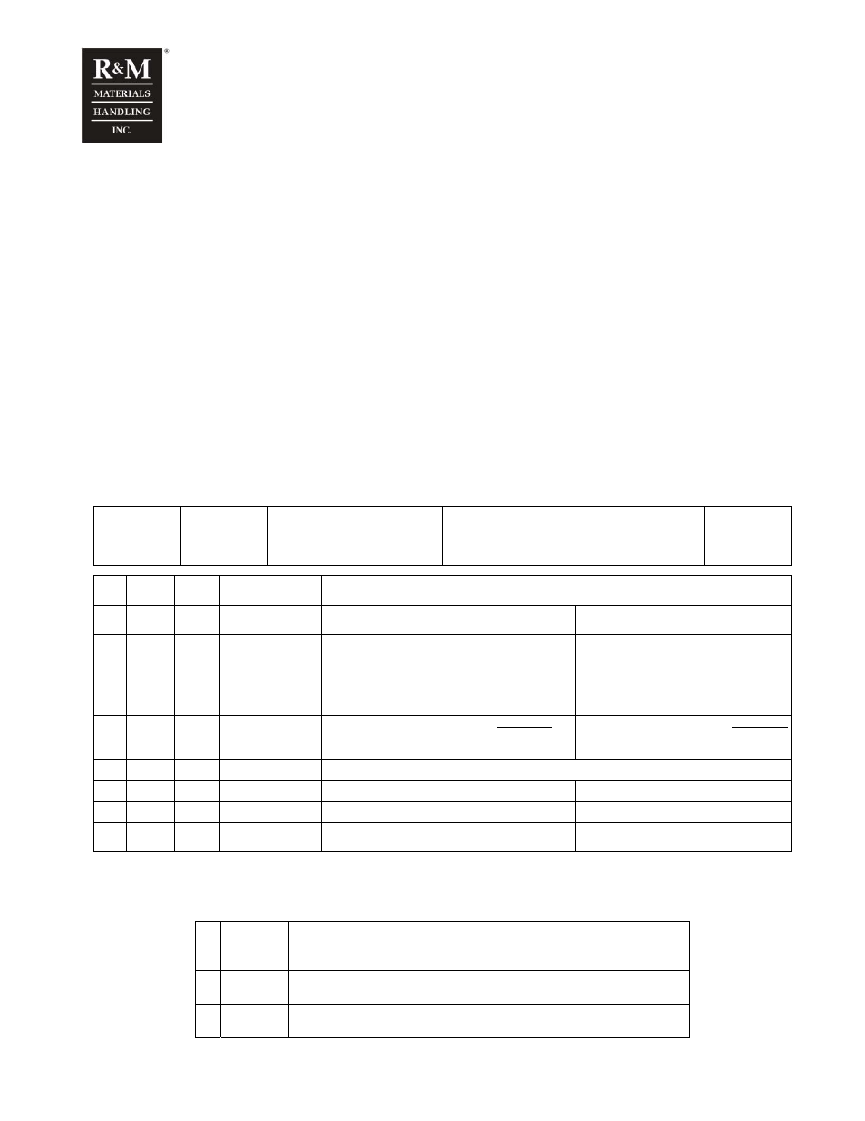
2.5 Factory code example (Factory: D2M)
D2M
007 F V 10 B 0 N
TR01
BT01
(ELE84)
(ELE85)
(ELE84)
(ELE85)
(ELE02)
ELE97
1-3 4-6 7 8 9,10 11 12 13
Pos. Code
Feature
code
Feature Available
properties
1-3
D2M
TR01
BT01
Device name
D2M
TR01 Type of trolley travel control
BT01 Type of bridge travel control
4-6
007
(ELE84)
(ELE85)
Power rating class
002 – 022
7
F
(ELE84)
(ELE85)
Supply voltage
F
380 – 500 VAC, 50/60 Hz
ELE84 Trolley travel inverter power rating
ELE85 Bridge travel inverter power rating
Values are composed of two features,
Power rating class and Supply voltage.
e.g. 007F = ELE84/ELE85 value
8
V
(ELE02) Control voltage
Y
P
42VAC, 50/60 Hz
48VAC, 50/60 Hz
ELE02 value
48
T
V
115VAC, 50/60 Hz
230VAC, 50/60 Hz
ELE02 value
115
230
9,10
10
Revision code
The latest revision may differ.
11
B
Braking resistor type A
External resistor, D2M 018 – 022 (002-004 as option) B
Internal resistor, D2M 002 – 015
12
0
Mounting
0
Standard panel
W
Wall mounting, D2M002 (003-004 as option)
13
N
ELE97 EMC
level
S
N
Standard, without EMC filters (grounded network)
EMC, Second environment (grounded network)
0
IT network (non-grounded network)
2.6 Description of the control modes
There are three main control modes with 8 different choices:
1
EP
Electronic potentiometer function.
•
Stepless control using a 2-step controller.
•
EP3 stepless control using a 3-step controller.
2
MS
Multistep control (up to 5 steps)
•
Requires programmable digital inputs for speed reference steps
3
AU
Automation control for any control device with an output in the range of 0 – 10V
•
E.g. radio controls, process computers.