12 drawings, 1 description of terminals and wirings – R&M Materials Handling VARIABLE SPEED CONTROLS ControlMaster Select Service Manual User Manual
Page 37
R&M Materials Handling, Inc.
4501 Gateway Boulevard
Springfield, Ohio 45502
P.: (937) 328-5100
FAX: (937) 325-5319
37/46
R&M Materials Handling, Inc. reserves the right to alter or amend the above information without notice.
12 DRAWINGS
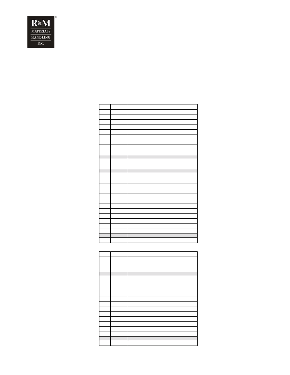
12.1 Description of terminals and wirings
The control unit of the frequency converter is integrated to the power unit in 002 and it is separated in
bigger models. Control board and additional I/O board (NXOPTB9) connections are listed below.
Terminals 003F – 011F
No
Name Description, signal level
PE
L1
L1
Power supply, phase 1
L2
L2
Power supply, phase 2
L3
L3
Power supply, phase 3
B+ R+
Braking
resistor
R- R-
Braking
resistor
U/T1
U/T1 Motor output, phase 1
V/T2
V/T2
Motor output, phase 2
W/T3 W/T3 Motor output, phase 3
31 BD1
DC
brake
supply
1
32 BD2
DC
brake
supply
2
4
T12
Reserved for thermistors connections
5
OLE
External control voltage, 48/115/230Vac
6
OLE
External control voltage, 48/115/230Vac
7
K7-5
Free NO-contact of K7
8
K7-6
Free NO-contact of K7
36
ONE Neutral of external control voltage OLE
38
S1
Direction 1 run command
39
S2
Direction 2 run command
40 DID3
Multi
Function
Input
41 DID4
Multi
Function
Input
42 DID5
Multi
Function
Input
47
OLE
External control voltage, 48/115/230Vac
PE
Terminals 015 – 022
No
Name
Description, signal level
PE
31 BD1 DC
brake
supply
1
32 BD2 DC
brake
supply
2
4
T12
Reserved for thermistors connections
5
OLE
External control voltage, 48/115/230Vac
6
OLE
External control voltage, 48/115/230Vac
7
K7-5
Free NO-contact of K7
8
K7-6
Free NO-contact of K7
36
ONE
Neutral of external control voltage OLE
38
S1
Direction 1 run command
39
S2
Direction 2 run command
40 DID3 Multi
Function
Input
41 DID4 Multi
Function
Input
42 DID5 Multi
Function
Input
47
OLE
External control voltage, 48/115/230Vac
PE