4 components, 1 inverter, 1 power supply unit (pss) – R&M Materials Handling VARIABLE SPEED CONTROLS ControlMaster Select Service Manual User Manual
Page 15
R&M Materials Handling, Inc.
4501 Gateway Boulevard
Springfield, Ohio 45502
P.: (937) 328-5100
FAX: (937) 325-5319
15/46
R&M Materials Handling, Inc. reserves the right to alter or amend the above information without notice.
4 COMPONENTS
4.1 Inverter
Inverter (D2S) includes a Power supply unit (PSS) and a Control unit (CSS), which are separate parts.
PSS includes supply, brake resistor and motor connections. IGBTs are located within the PSS.
Microprocessors and Application Special Integral Circuit (ASIC) Chip are located within the CSS. Same
CSS can be used for all models of the D2S.
D2S (F-series)
I
in
(A)
I
max
at
1min IA)
Weight
kg
Weight
lbs
D2S002NF1e00
5.0 7.6 1.9 4
D2S003NF1e00
8 12 5 11
D2S004NF1e00 10 15 5 11
D2S005NF1e00 13 20 8.1 18
D2S007NF1e00 18 27 8.1 18
D2S011NF1e00 24 36 8.1 18
D2S015NF1e00 32 48 18.5
41
D2S018NF1e00 42 63 18.5
41
D2S022NF1e00 48 72 18.5
41
e defines EMC level ( 0 = EMC level 0, N = EMC level S/N )
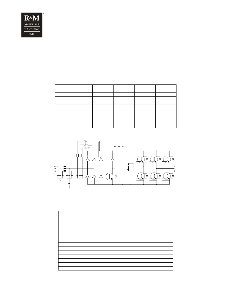
The main circuit diagram of D2S 007 – D2S 015
DC-
DC+
BR
B+
B-
WH_G
WH_D
WL_D
VH_G
VH_D
VL_G
VL_D
BRK_G
BRK_D
U/T1
V/T2
W/T3
L1
L2
L3
UH_D
UH_G
UL_G
UL_D
WL_G
4.1.1 Power supply unit (PSS)
Power supply unit (PSS) includes the main circuit components. PSS has connectors for supply cables,
motor cables and braking resistor cables. PSS also includes a connector for CSS-connection.
Main supply voltage terminals
L1 Mains
L1
L2 Mains
L2
L3 Mains
L3
PE Protective
earth
(Ground)
DC-bus terminals
B-
DC-bus negative (003-022)
B+ DC-bus
positive
(003-022)
R-
Brake resistor negative (003-022)
BR+
DC-bus positive / Brake resistor positive (002)
BR-
Brake resistor negative (002)
Motor output voltage terminals
U/T1 Motor
U/T1
V/T2 Motor
V/T2
W/T3 Motor
W/T3