2 control unit (css), 3 i/o extension board, 2 control voltage transformer – R&M Materials Handling VARIABLE SPEED CONTROLS ControlMaster Select Service Manual User Manual
Page 16
R&M Materials Handling, Inc.
4501 Gateway Boulevard
Springfield, Ohio 45502
P.: (937) 328-5100
FAX: (937) 325-5319
16/46
R&M Materials Handling, Inc. reserves the right to alter or amend the above information without notice.
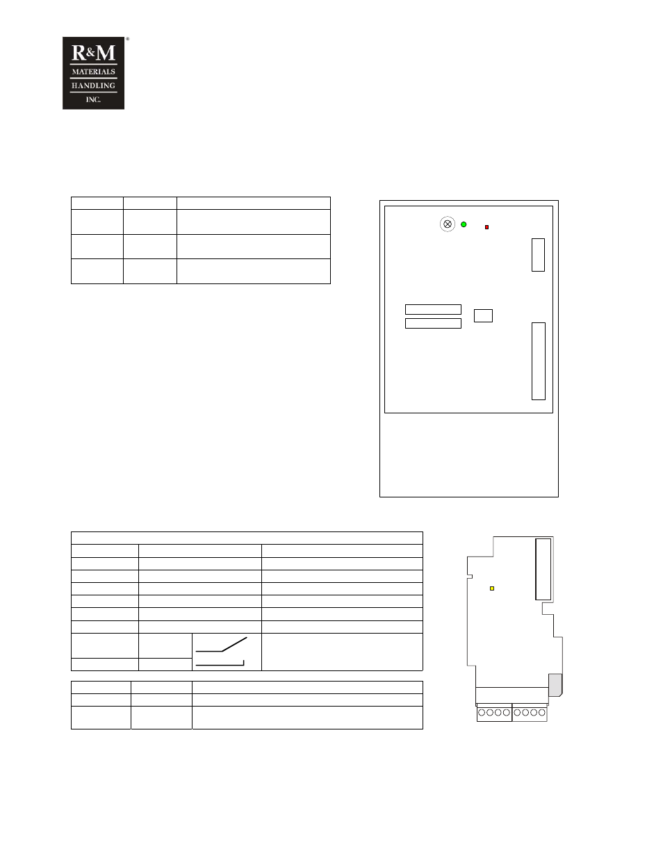
4.1.2 Control unit (CSS)
Control unit (CSS) includes a control board with five board slots for option boards and a control keypad
for parameter adjustments. Inverter uses only one of the existing slots and is used to connect I/O
extension board. The CSS is connected to PSS through a connector.
Green
Red
Status
ON OFF Everything
is
OK.
blinking
ON
Fault
blinking
blinking
In process of software downloading
RED
GREEN
K
E
Y
P
A
D
I/O
E
xt
en
si
on
B
oa
rd
ANALOG TERMINAL
ROA1
A
B
C
D
ANALOG TERMINAL
4.1.3 I/O Extension board
NXOPTB9 / I/O Extension board
ID: 52305691
Terminal
Signal name
Description
1 DID1
42-240Vac
50/60Hz
2 DID2
42-240Vac
50/60Hz
3 DID3
42-240Vac
50/60Hz
4 DID4
42-240Vac
50/60Hz
5 DID5
42-240Vac
50/60Hz
6
COM
Common for DID1-DID5
7
ROD1
8 ROD1
Relay output, 250V 8A, normal open
For brake contactor control
LED Blinking
Status
Yellow 0.25Hz OK
Yellow 4Hz
Board internal fault or communication fault with control
unit
YELLOW
1
2
3
4
5
6
7
8
4.2 Control voltage transformer
Power of control voltage transformer has to be n * 50VA + 50VA (min. 250VA), n = number of inverters.
This power does not have to be added to otherwise needed transformer power.