R&M Materials Handling VARIABLE SPEED CONTROLS ControlMaster Select Service Manual User Manual
Page 25
R&M Materials Handling, Inc.
4501 Gateway Boulevard
Springfield, Ohio 45502
P.: (937) 328-5100
FAX: (937) 325-5319
25/46
R&M Materials Handling, Inc. reserves the right to alter or amend the above information without notice.
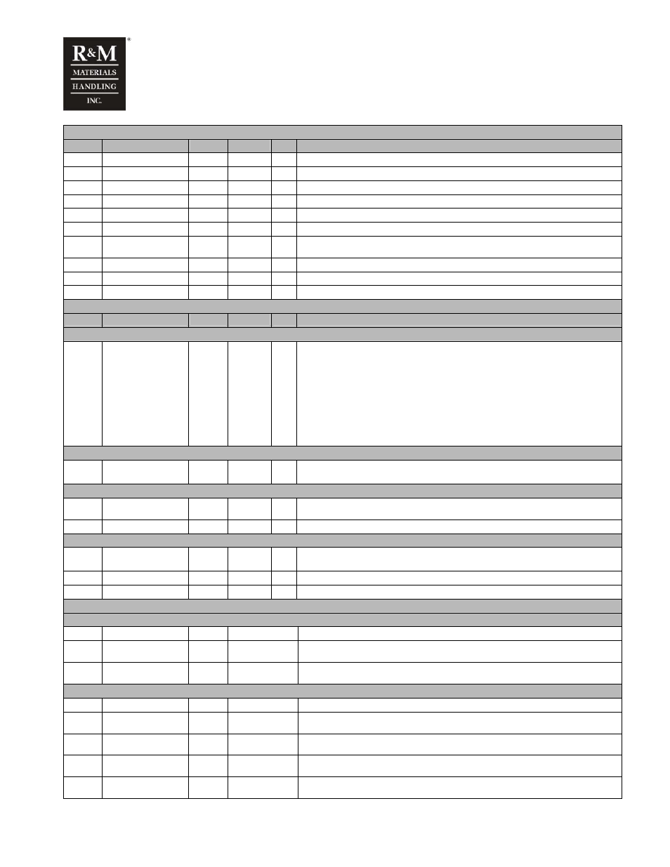
M2 Monitoring
Code
Name
Min
Max
Unit Description
V2.1
K7
0
1
State of relay output ROD1, which controls brake contactor
V2.2
ROA1
0
1
State of relay output ROA1
V2.3
DID states
.00000
.11111
State of digital input DID1-DID5, see note
V2.4
Ain1 Input
0.00
10.00
V
Value of analog input Ain1
V2.5
Motor Current
A
Measured motor current
V2.6
Motor Voltage
V
Calculated motor voltage
V2.7 Heat
Sink
Temperature
°C
Temperature of heat sink.
V2.8
DC-link Voltage
V
Actual value of measured DC-link voltage.
V2.9 Frequency
Reference
Hz
V2.10
Output Frequency
Hz
Output frequency to the motor
M3 System Menu
Code
Name
Min
Max
Unit Description
S3.3 Copy parameters
P3.3.1
Parameter sets
0 = Select
1 = Store user parameters
2 = Load user parameters
3 = Store factory parameters
4 = Load factory parameters
5 = Reset parameters
6 = Fault
7 = Wait
8 = OK
S3.5 Security (not used)
P3.5.2 Parameter
lock
0 = Change Enabled
1 = Change Disabled
S3.6 Keypad settings
P3.6.1
Default page
Display goes to Default page after Timeout time. If value 0 is selected, this feature is not
active. Default value 2.10 “Output Frequency”
P3.6.3
Timeout time
0
65535
s
Display goes to Default page after Timeout time.
S3.7 Hardware settings
P3.7.2
Fan control
0 = Continuous, default
1 = Temperature
P3.7.3
Not
used
P3.7.4
Not
used
S3.8 System info
S3.8.1 Counters menu
C3.8.1.1 MWh
counter
KWh
C3.8.1.2 Operating
days
Counter
hh:mm:ss
C3.8.1.3 Operating
hours
Counter
hh:mm:ss
S3.8.2 Trip counters
T3.8.2.1 MWh trip counter
KWh
P3.8.2.2 Clear MWh trip
counter
T3.8.2. 3 Operating days trip
counter
T3.8.2.4 Operating
hours
trip
Counter
hh:mm:ss
P3.8.2.5 Clear operating time
Counter