Troubleshooting – B&B Electronics GW-7552 - Manual User Manual
Page 65
GW-7552 PROFIBUS/MODBUS GATEWAY User Manual (Version 1.40, Apr/2012) PAGE: 65
6. Troubleshooting
The troubleshooting list can help users to resolve the problems when using the GW-
7552. If the problem still can't be solved, please contact with technical staff of ICP
DAS.
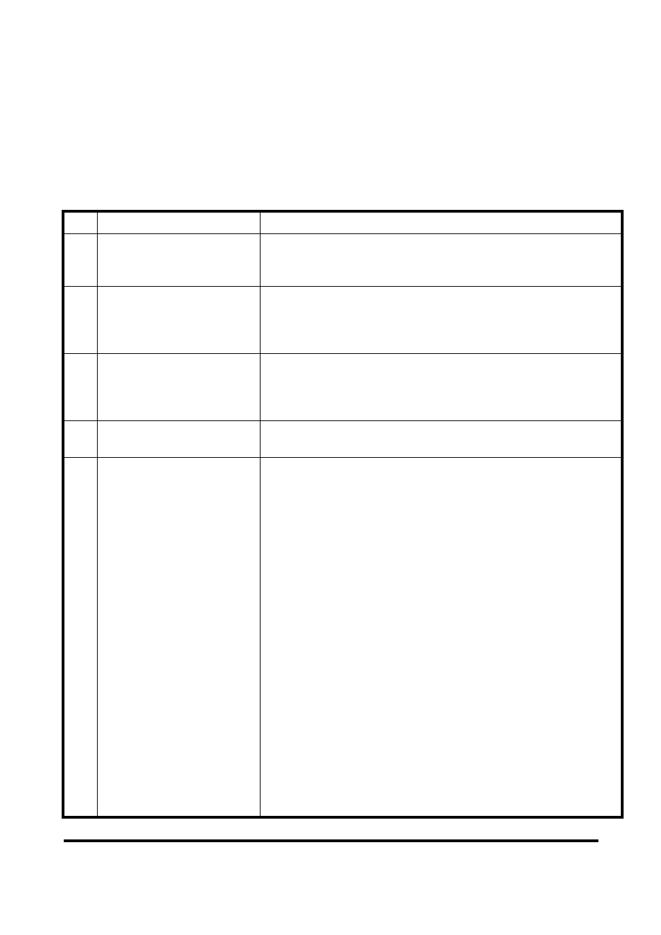
Table 17 Errors and solutions
Item Trouble state
Solution
1
'PWR' LED indication of
the GW-7552 is always
turned off
The power supply of GW-7552 has some problems. Please check
the wire connection of the power and the voltage is between
10~30VDC.
2
'ERR' LED indication of the
GW-7552 is always turned
on
That means the GW-7552 isn't connecting to the PROFIBUS
master station. Please check the wire connection and the
PROFIBUS master station. The configuration and address of
GW-7552 in the PROFIBUS master station are not correct.
3
'ERR' LED indication of the
GW-7552 is flashing fast
It means the GW-7552 is in setting mode and connects with
Utility. Please close Utility and set the GW-7552 to operation
mode (please refer section 2.6 Normal/Setting Dip Switch and
section 4.6.2 Output data area and communication command).
4
'ERR' LED indication of the
GW-7552 is flashing slow
It means the GW-7552 has diagnostic messages. Please check
diagnostic messages in the Profibus master station.
5
Profibus master station can
not communicate with the
Modbus device, when
“RUN LED” of the GW-
7552 is light and “ERR
LED” of the GW-7552 is
dark.
a. Please confirm the GW-7552 is working in operation mode
and avoid clearing diagnostic message by communication
command (please refer section 2.6 Normal/Setting Dip
Switch and section 4.6.2 Output data area and
communication command).
b. Please confirm the connection between the GW-7552 and
Modbus device.
c. Please confirm Com Port setting of the GW-7552 (please
refer section 4.3 The Configuration of the common
parameters) the same as Com Port setting of the Modbus
device.
d. Please confirm module ID of the GW-7552 (please refer
section 4.3 The Configuration of the common parameters and
section 4.4 The Configuration of the modules) the same as
Modbus address of Modbus device.
e. Please confirm Setting of Start Address and NO. of
Relay/Coil is correct (please refer section 4.4 The
Configuration of the modules).
f. Please confirm the output data put in correct address and have
changed value of byte 0 to trigger the output command, when
output data can not send to modbus device in output data area
of Profibus master (please refer section 4.6.2 Output data area
and communication command).