B&B Electronics GW-7552 - Manual User Manual
Page 39
GW-7552 PROFIBUS/MODBUS GATEWAY User Manual (Version 1.40, Apr/2012) PAGE: 39
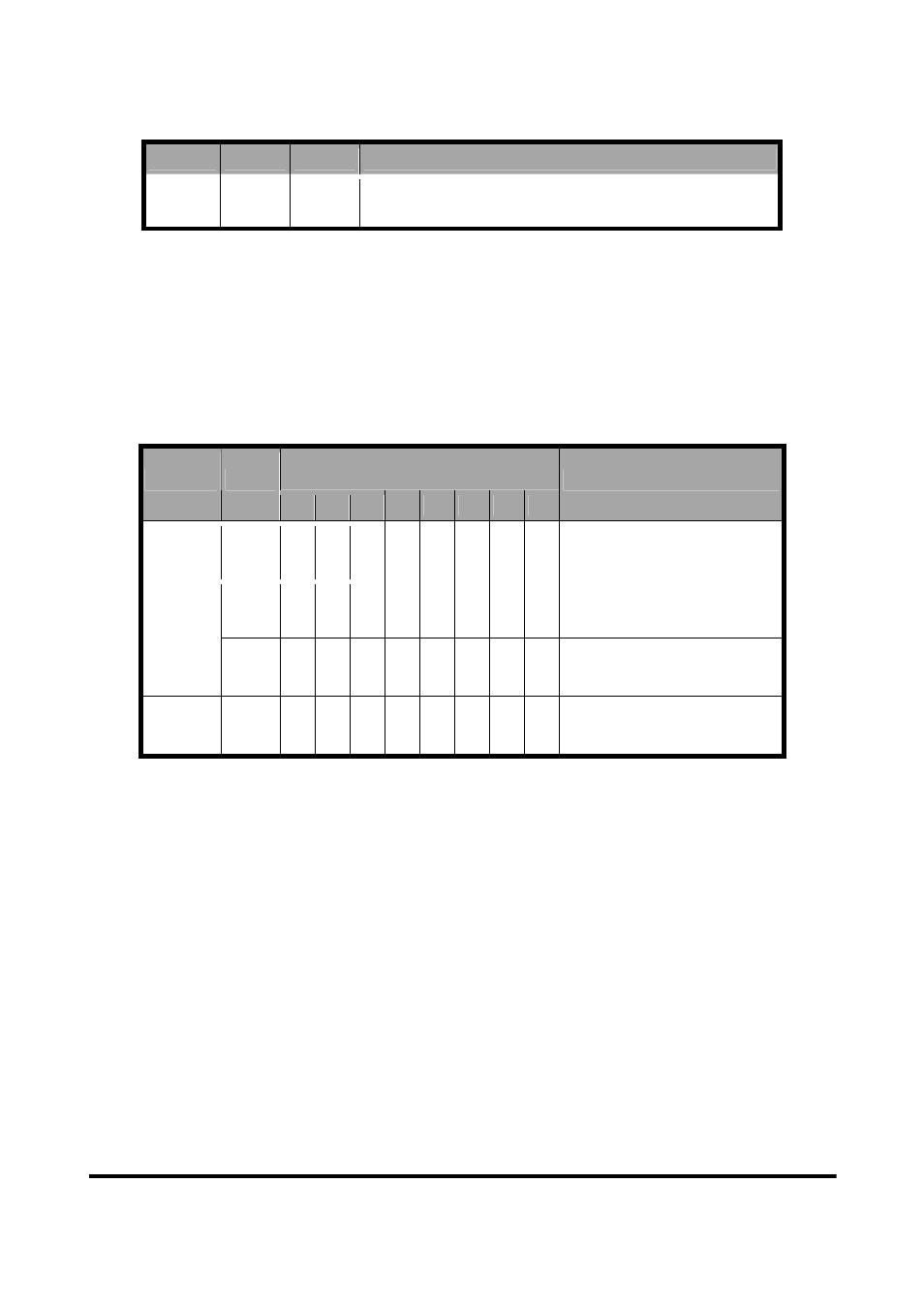
Table 13 Input data area
Module
Byte
Data
Description
Input
module
0~127
Data Receive data
4.6.2 Output data area and communication command
The maximum length of output data is 131 bytes. Before arrange the output
module, the user must arrange and configure the system setting module. The
first three bytes belong to communication commands, as shown in table 14. The
user can change data and I/O state of Modbus slave device or DI/DO/AI/AO
data of GW-7552 by modify data of output module.
Table 14 Output data area
Bit Position
Module Byte
7
6
5
4
3
2
1
0
Description
0
Data output command
1
- - - -
-
-
SM DC Control bit
System
setting
module
2
Output module select
Output
module
3~130
Output data
●
Data output command(byte 0)
a. When Modbus type is master
When this byte is changed, Profibus master device will send data of
output module to DO/AO data of GW-7552 and then GW-7552 will
send query message to Modbus slave device for change data or output
state of Modbus slave device.
b. When Modbus type is slave
When this byte is changed, Profibus master device will send data of
output module to DO/AO data of GW-7552.
PS: When the user use this byte to trigger “data output command”, the
user must increase this byte in order (ex: 0->1, 1->2,…, 255->0) or else
the GW-7552 will send a diagnostic message to the Profibus master
(please refer section 4.5 Diagnostic messages).