Controls, indicators and connector specifications – B&B Electronics VESR9xx - Fiber Models - Manual User Manual
Page 50
Appendix B
www.bb-elec.com
www.bb-europe.com
44
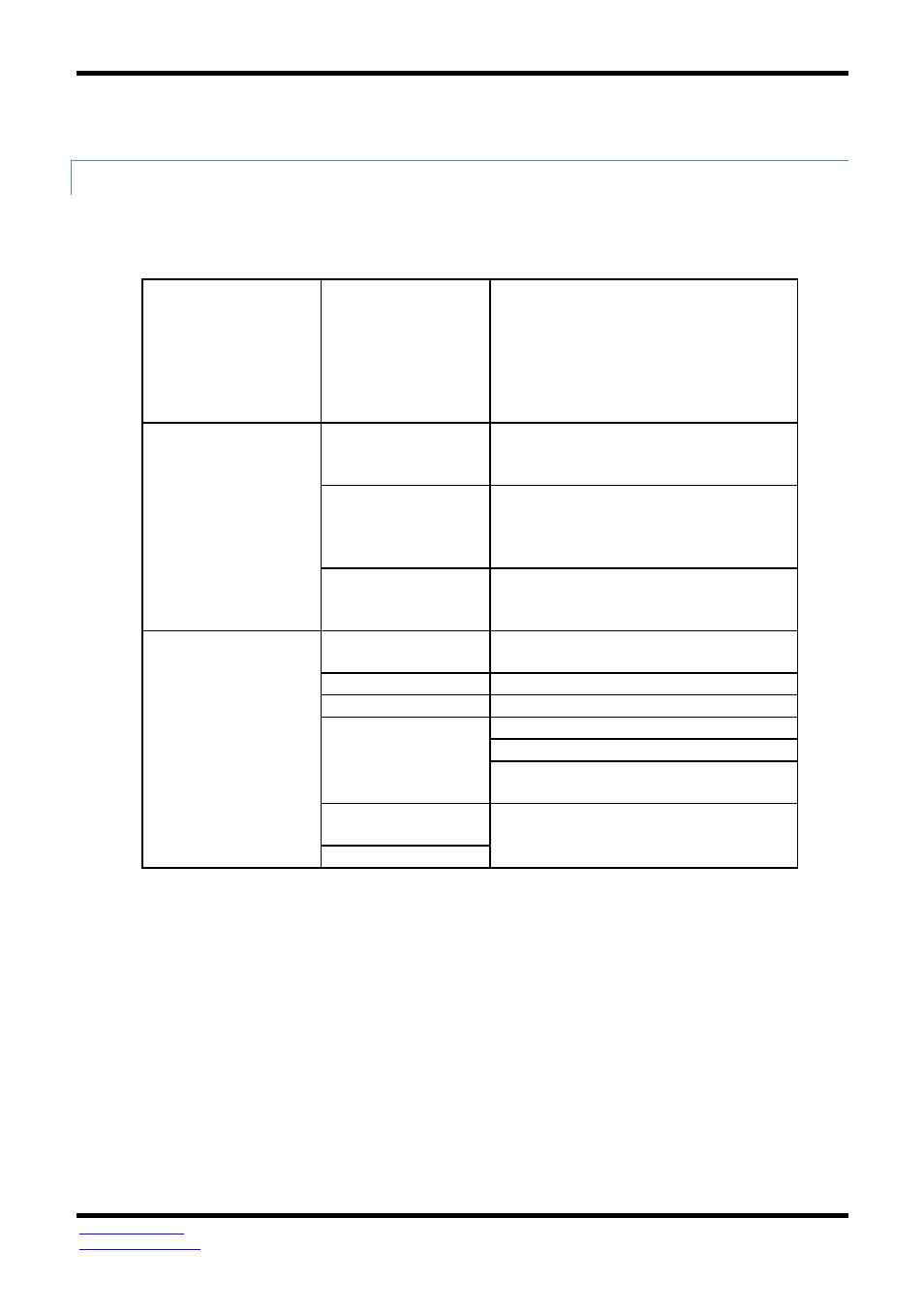
CONTROLS, INDICATORS AND CONNECTOR SPECIFICATIONS
Switches
Reset button
Hold in for 0 to 2 seconds for hardware
reset
Hold in for 2 to 10 seconds for Console
Mode (Do a hardware reset or recycle
power to exit Console Mode)
Hold in for more than 10 seconds to reset to
factory defaults
Indicators
Serial LED
(one per port)
Color = Green
On = Port open
Blink = Data traffic
Link LED (VESR 90x)
E1 / E2 LED
(VER92x)
Color = Green
On = 100BaseTX
Off = 10BaseT
Blink = Data traffic
Ready LED
Color = Green
Blink (once per second) = System OK
Off = System NOT OK
Connectors
10BaseT/100BaseTX
Ethernet
Single RJ-45F (8 pin)
SC fiber
SC connector
ST fiber
ST connector
Serial
ESR901-x: one DB-9M connector
ESR902D-x: Two DB-9M connectors
ESR902T-x: Two pluggable lockable 5.08
mm terminal blocks
DC Power
5.08mm 2-position pluggable, lockable
terminal block
- USOPTL4DR-LS - Datasheet (2 pages)
- ZXT9-IOA-KIT - Manual (75 pages)
- ADAM-6066 - Manual (272 pages)
- 855-11619--57 - Datasheet (2 pages)
- 851-10904 - Datasheet (2 pages)
- SS-BLT-100PR - Quick Start Guide (1 page)
- ISOCON-6 - Datasheet (2 pages)
- I-7060 - Manual (64 pages)
- AMU864 - Datasheet (2 pages)
- 714FX6-SC_ST - Manual (154 pages)
- 422LP25R - Datasheet (2 pages)
- ZP9D-115RM-LR - Manual (54 pages)
- EKI-6311GN-EU - Manual (56 pages)
- ZZ24D-NA(NB,NC,ND)-SR - Quick Start Guide (4 pages)
- ESCLP-100 - Manual (23 pages)
- 806-39753 - Datasheet (1 page)
- 485SD9RJ - Datasheet (1 page)
- 712FX4-SC_ST - Manual (154 pages)
- 850-18610 - Manual (18 pages)
- ESW208 Series - Datasheet (2 pages)
- VESR321_ML_SL - Quick Start Guide (3 pages)
- OP10 - Datasheet (1 page)
- RT3G-300_310_320_330_340-W - Configuration Manual (79 pages)
- EIRHP305-T - Datasheet (2 pages)
- EIRSP1 - Datasheet (1 page)
- 422TTL33 - Datasheet (2 pages)
- 485DRCI - Quick Start Guide (2 pages)
- I-7021_P - Datasheet (2 pages)
- NTSA-CAT5E - Datasheet (2 pages)
- 485COSR - Datasheet (2 pages)
- 855-10619--57 - Datasheet (2 pages)
- UH401SL_2KV - Datasheet (2 pages)
- 105FXE-SC(ST)-15-POE - Manual (19 pages)
- 102MC-FL_SC_ST - Manual (23 pages)
- CBL00302 - Datasheet (1 page)
- 850-18100--27 - Datasheet (2 pages)
- 850-10953-DC - Datasheet (2 pages)
- ESR904 - Datasheet (2 pages)
- 308TX-N - Datasheet (3 pages)
- 422LP25N - Datasheet (2 pages)
- 708FX2-SC_ST - Datasheet (3 pages)
- MESR321_SL_ML - Datasheet (2 pages)
- SL2736-698 - Quick Start Guide (8 pages)
- I-7188E Series - Datasheet (1 page)
- ANT-PAD58-19 - Datasheet (1 page)