Electrical characteristics (continued) – Rainbow Electronics ATA6834 User Manual
Page 17
17
9122B–AUTO–10/08
ATA6833/ATA6834 [Preliminary]
2.8 Output current limit
V
MODE
= V
INT
, V
BAT
> 7V
V
MODE
= GND, V
BAT
> 5.5V
I
Load
@ RESET,
150°C < T
J
< 200°C
VCC
I
OS1
70
70
320
320
mA
C
2.12 HIGH threshold VMODE
V
VMODE H
4.0
V
A
2.13 LOW threshold VMODE
V
VMODE L
0.7
V
A
3
Reset and Watchdog
3.1
V
CC
threshold voltage level
for /RESET
VMODE = VINT
(VMODE = GND)
V
tHRESH
4.1
(2.7)
4.7
(3.0)
V
A
3.2 Hysteresis of /RESET level
HYS
RESth
0.2
V
A
3.3 Length of pulse at /RESET
t
res
8
12
ms
A
3.4
Length of short pulse at
/RESET
t
resshort
1.8
2.2
ms
A
3.5 Wait for the first WD trigger
t
d
400
600
ms
A
3.6
Time for VCC < V
tHRESL
before activating /RESET
t
delayRESL
2
µs
C
3.8 Watchdog oscillator period
R
RWD
= 33 k
Ω
T
OSC
11.09
13.55
µs
A
3.12 Close window
t1
980
×
T
OSC
A
3.13 Open window
t2
780
×
T
OSC
A
3.14
Output low-level at pin
/RESET
I
OLRES
= 1 mA
V
OLRES
0.4
V
A
3.15
Internal pull-up resistor at
pin /RESET
R
PURES
5
10 15
k
Ω
D
4
LIN Transceiver
4.1 Low-level output current
Normal mode;
V
LIN
= 0V, V
RXD
= 0.4V
IL
RXD
2
mA
D
4.2 High-level output current
Normal mode; V
LIN
= V
BAT
V
RXD
= V
CC
– 0.4V
IH
RXD
–2
mA
D
4.3
Driver recessive output
voltage
V
TXD
= V
CC
; I
LIN
= 0 mA
V
BUSrec
0.9
×
VBAT
V
A
4.4
Driver dominant voltage
V
BUSdom_DRV_LoSUP
V
VBAT
= 7.3V
R
load
= 500
Ω
V
_LoSUP
1.2
V
A
4.5
Driver dominant voltage
V
BUSdom_DRV_HiSUP
V
VBAT
= 18V
R
load
= 500
Ω
V
_HiSUP
2
V
A
4.6
Driver dominant voltage
V
BUSdom_DRV_LoSUP
V
VBAT
= 7.3V
R
load
= 1000
Ω
V
_LoSUP_1k
0.6
V
A
4.7
Driver dominant voltage
V
BUSdom_DRV_HiSUP
V
VBAT
= 18V
R
load
= 1000
Ω
V
_HiSUP_1k_
0.8
V
A
4.8 Pull up resistor to VS
serial diode required
R
LIN
20
47
k
Ω
A
4.9 Current limitation
V
BUS
= V
BAT_max
I
BUS_LIM
50
200
mA
A
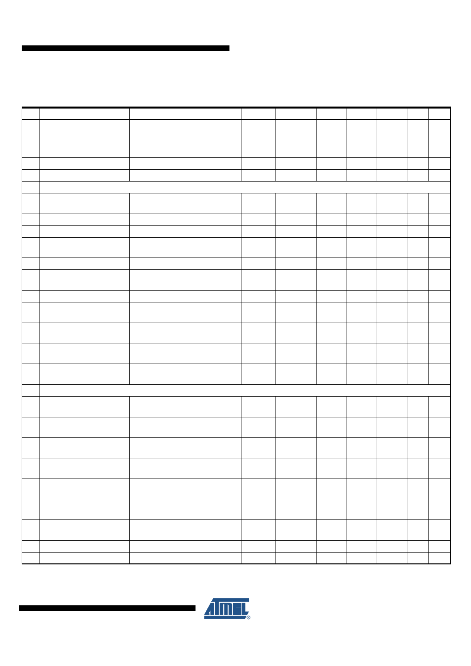
8.
Electrical Characteristics (Continued)
All parameters given are valid for 5.5V
≤
V
VBAT
≤
18V and for –40°C
≤
T
J
≤
150°C (200°C) unless stated otherwise. All values refer to PIN
GND. [xxx] Values for the ATA6834.
No. Parameters
Test Conditions
Pin
Symbol
Min.
Typ.
Max.
Unit Type*
*) Type means: A = 100% tested, B = 100% correlation tested, C = Characterized on samples, D = Design parameter