6 vg regulator – Rainbow Electronics ATA6834 User Manual
Page 10
10
9122B–AUTO–10/08
ATA6833/ATA6834 [Preliminary]
3.6
VG Regulator
The VG regulator provides a stable voltage to supply the low-side gate drivers and to deliver suf-
ficient voltage for the external low-side Power-NMOS transistors. Typically the output voltage is
12V. In order to guarantee reliable operation even with a low battery voltage, the VG regulator is
supplied by the charge pump output. For stability, an external ceramic capacitor of typically
470 nF has to be provided. There is no internal supervision of the VG output voltage.
3.7
Output Drivers and Control Inputs IL1-IL3, IH1-IH3
This IC offers six push-pull output drivers for the external low-side and high-side power-NMOS
transistors. To guarantee reliable operation, the low-side drivers are supplied by the VG regula-
tor while the high-side drivers are supplied directly by the charge pump. All drivers are designed
to operate at switching frequencies in the range of DC up to 50 kHz. The maximum gate charge
that can be delivered to each external Power-NMOS transistor at 50 kHz is 100 nC.
The output drivers are directly controlled by the digital input pins IL1 to IL3 and IH1 to IH3 (see
). All pins are equipped with an internal pull-down resistor. To operate the output driv-
ers properly the following requirements have to be fulfilled:
1.
Device is in Active Mode.
2.
In case of watchdog is enabled, at least one valid watchdog trigger has been accepted.
3.
The voltage at pin PBAT lies within its operation range. Neither undervoltage nor over-
voltage is present.
4.
The charge pump output voltage has been accepted as good, thus it exceeded
VCP
CPGOOD
.
5.
No overtemperature shutdown has occurred.
If a short circuit is detected by one of the sense inputs S1 to S3, the output drivers will be
switched off after a debounce time of 6 µs and the output DG1 will be flagged (see also
3.8 “Short Circuit Detection” on page 11
). The output drivers will be enabled again and DG1 will
be cleared with a rising edge at one of the control inputs (IL1 to IL3, IH1 to IH3).
Additional logic prevents short circuits due to switching on one power-NMOS transistor while the
opposite one in the same branch is switched on already.
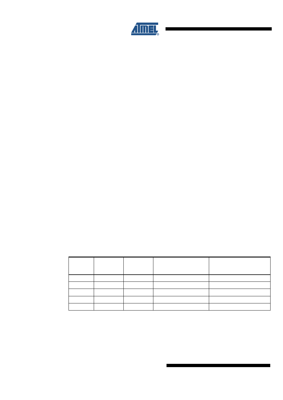
Table 3-1.
Status of the Output Drivers Depending on the Control Inputs
Mode
Control
Inputs
IL[1..3]
Control
Inputs
IH[1..3]
Driver Stage for External
Power MOS
L[1..3], H[1..3]
Comments
Sleep
X
X
OFF
Sleep Mode
Active
0
0
OFF
Active
1
0
L[1..3] ON, H[1..3] OFF
Active
0
1
H[1..3] ON, L[1..3] OFF
Active
1
1
OFF
Shoot-through protection