Operating range, Noise and surge immunity, Electrical characteristics – Rainbow Electronics ATA6834 User Manual
Page 15: Ied in, Section 8. “electrical characteristics” on
15
9122B–AUTO–10/08
ATA6833/ATA6834 [Preliminary]
6.
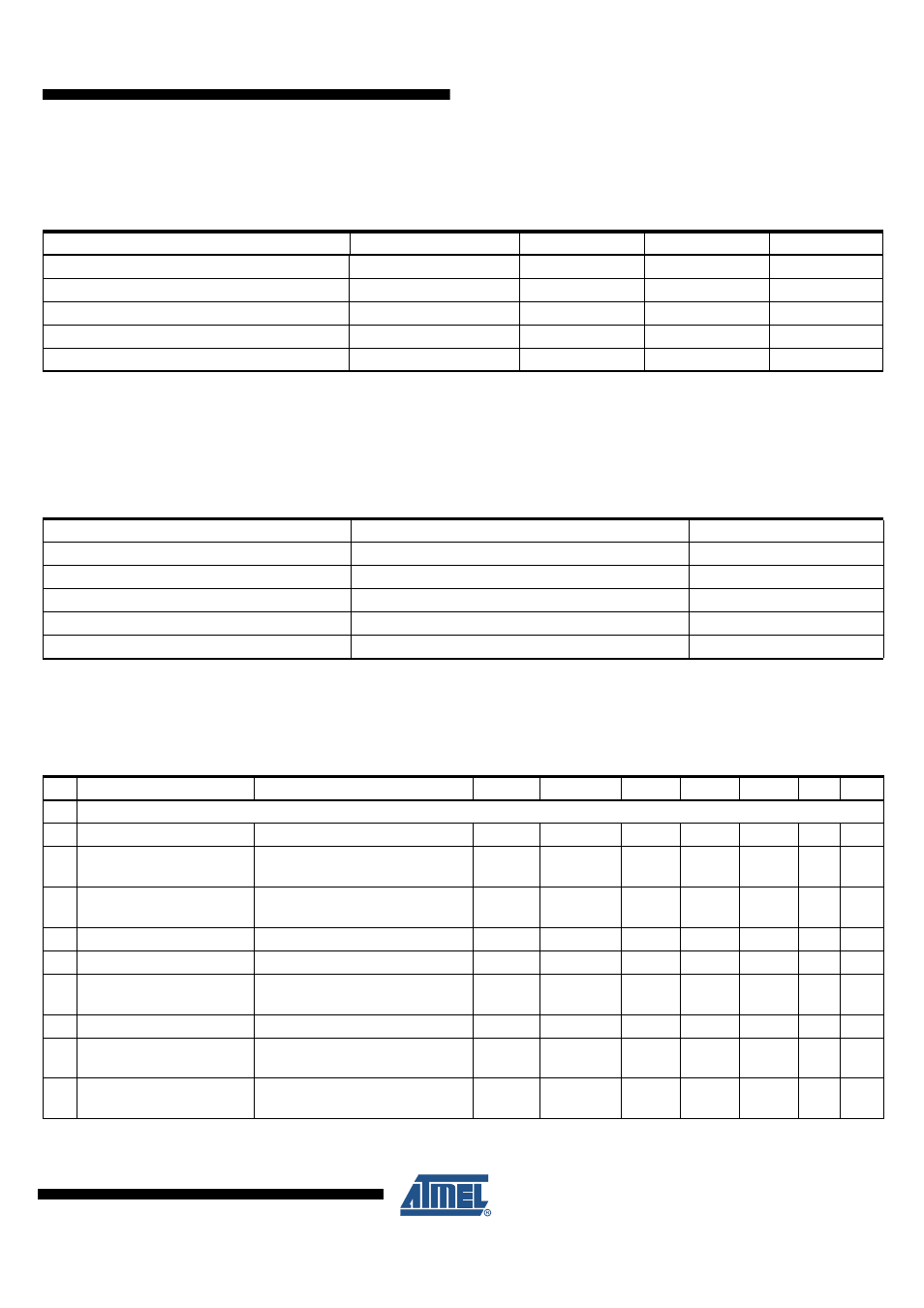
Operating Range
The operating conditions define the limits for functional operation and parametric characteristics of the device. Functionality outside these
limits is not implied unless otherwise stated explicitly. [xxx] Values for the ATA6834
Parameters
Symbol
Min
Max
Unit
Operating supply voltage
(1)
V
VBAT
5.5 V
THOV
(4)
V
Operating supply voltage
(2)
V
VBAT
4.3
5.5
V
Operating supply voltage
(3)
(t = 500 ms)
V
VBAT
V
THOV
(4)
40
V
Ambient temperature range
T
A
–40
+150
°C
Junction temperature range
T
J
–40
+150 (200)
°C
Notes:
1. Full functionality
2. Output drivers are switched off, extended range for parameters for voltage regulators
3. Output drivers and charge pump are switched off
4. Voltages higher V
THOV
for maximum 500 ms
7.
Noise and Surge Immunity
Parameters
Standard and Test Conditions
Value
Conducted interferences
ISO 7637-1
Level 4
(1)
Conducted disturbances
CISP25
Level 5
ESD (Human Body Model)
ESD S 5.1
±2 kV
ESD (Human Body Model)
DIN EN61000-4-2, Pin LIN, VBAT, PBAT to GND
±6 kV
Latch-up immunity
JESD78, AEL-Q100 (004)
Class II, level A
Note:
1. Test pulse 5: V
bat max
= 40V
8.
Electrical Characteristics
All parameters given are valid for 5.5V
≤
V
VBAT
≤
18V and for –40°C
≤
T
J
≤
150°C (200°C) unless stated otherwise. All values refer to PIN
GND. [xxx] Values for the ATA6834.
No. Parameters
Test Conditions
Pin
Symbol
Min.
Typ.
Max.
Unit Type*
1
Power Supply and Supervisor Functions
1.1 Current consumption V
VBAT
V
VBAT
= 13.5V
(1)
VBAT
I
VBAT
7
mA
A
1.3
Current consumption V
VBAT
in Standby Mode
V
VBAT
= 13.5V
VBAT
I
VBAT
65
µA
A
1.4
Current consumption V
VBAT
in Standby Mode
V
PBAT
= 13.5V
PBAT
I
VPBAT
TBD
µA
A
1.5 Internal power supply
V
VBAT
> 7V
VINT
V
VINT
4.7
5.0
5.3
V
A
1.6 Overvoltage threshold
PBAT
V
THOV
19.8
22.3
V
A
1.7
Overvoltage threshold
hysteresis
PBAT
V
TOVhys
1
1.5
V
A
1.8 Undervoltage threshold
PBAT
V
THUV
5.0
5.5
V
A
1.9
Undervoltage threshold
hysteresis
PBAT
V
TUVhys
0.2
0.4
V
A
1.10 R
DSON
VBAT-Switch switch
V
VBAT
= 13.5V,
I
VBATSW
= –15 mA
VBATSW R
ON_VBATSW
100
Ω
A
*) Type means: A = 100% tested, B = 100% correlation tested, C = Characterized on samples, D = Design parameter