I-channel offset, I-channel full-scale voltage adjust, Q-channel offset – Rainbow Electronics ADC08D1000 User Manual
Page 22: 0 functional description
1.0 Functional Description
(Continued)
Bit 10
nDE: DDR Enable. When this bit is set to 0b,
data bus clocking follows the DDR (Dual
Data Rate) mode whereby a data word is
output with each rising and falling edge of
DCLK. When this bit is set to a 1b, data bus
clocking follows the SDR (single data rate)
mode whereby each data word is output with
either the rising or falling edge of DCLK , as
determined by the OutEdge bit.
POR State: 0b
Bit 9
OV: Output Voltage. This bit determines the
LVDS outputs’ voltage amplitude and has the
same function as the OutV pin that is used in
the normal control mode. When this bit is set
to 1b, the "normal" output amplitude of 600
mV
P-P
is used. When this bit is set to 0b, the
reduced output amplitude of 450mV
P-P
is
used.
POR State: 1b
Bit 8
OE: Output Edge. This bit selects the DCLK
edge with which the data words transition in
the SDR mode and has the same effect as
the OutEdge pin in the normal control mode.
When this bit is 1, the data outputs change
with the rising edge of DCLK+. When this bit
is 0, the data output change with the falling
edge of DCLK+.
POR State: 0b
Bits 7:0
Must be set to 1b.
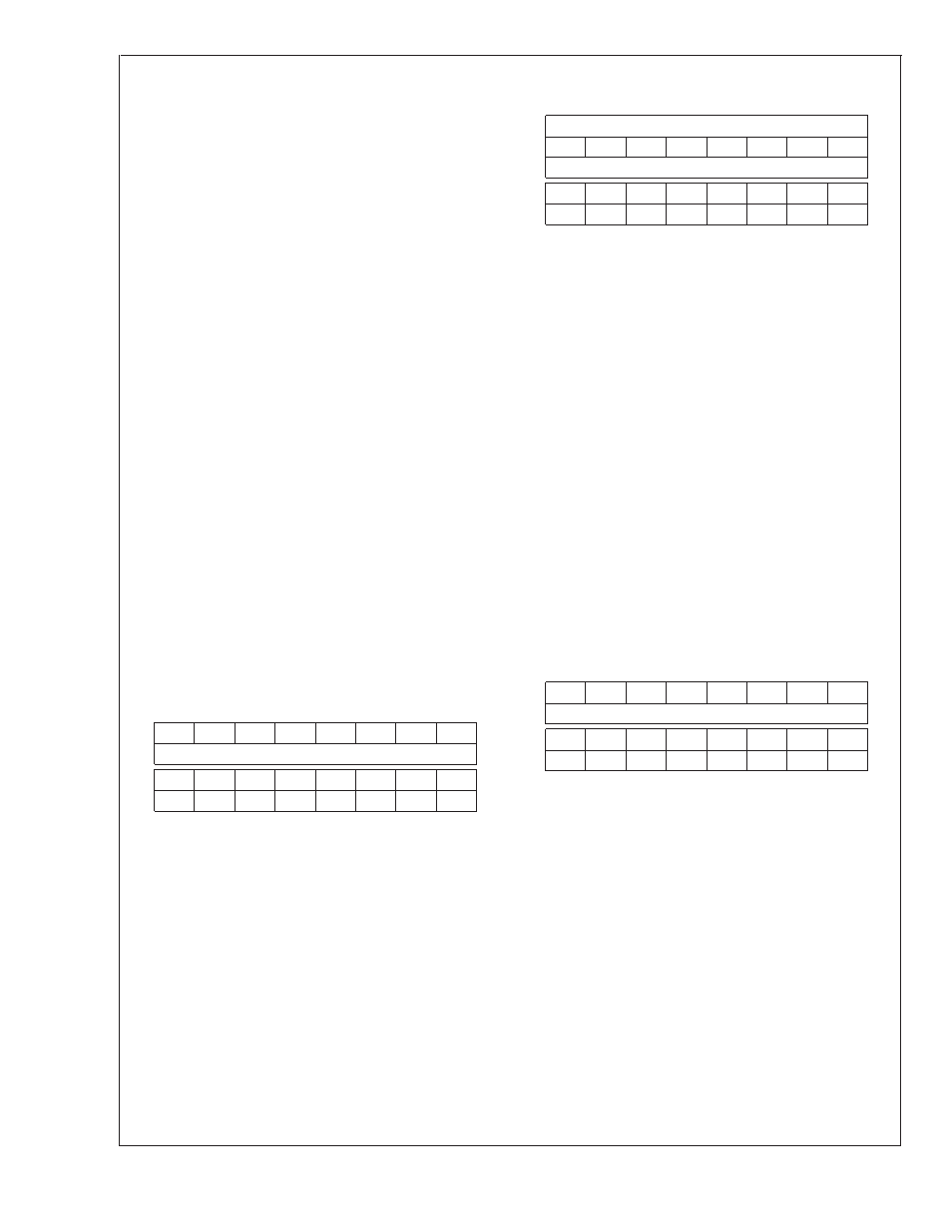
I-Channel Offset
Addr: 2h (0010b)
W only (0x007F)
D15
D14
D13
D12
D11
D10
D9
D8
(MSB)
Offset Value
(LSB)
D7
D6
D5
D4
D3
D2
D1
D0
Sign
1
1
1
1
1
1
1
Bits 15:8
Offset Value. The input offset of the
I-Channel ADC is adjusted linearly and
monotonically by the value in this field. 00h
provides zero nominal offset, while FFh
provides a nominal
±
45 mV of offset. Thus,
each code step provides 0.176 mV of offset.
POR State: 0000 0000 b
Bit 7
Sign bit. 0b gives positive offset, 1b gives
negative offset.
POR State: 0b
Bit 6:0
Must be set to 1b
I-Channel Full-Scale Voltage Adjust
Addr: 3h (0011b)
W only (0x807F)
D15
D14
D13
D12
D11
D10
D9
D8
(MSB)
Adjust Value
D7
D6
D5
D4
D3
D2
D1
D0
(LSB)
1
1
1
1
1
1
1
Bit 15:7
Full Scale Voltage Adjust Value. The input
full-scale voltage or gain of the I-Channel
ADC is adjusted linearly and monotonically
with a 9 bit data value. The adjustment range
is
±
20%
of
the
nominal
700
mV
P-P
differential value.
0000 0000 0
560mV
DIFF
1000 0000 0
Default Value
700mV
DIFF
1111 1111 1
840mV
DIFF
For best performance, it is recommended
that the value in this field be limited to the
range of 0110 0000 0b to 1110 0000 0b. i.e.,
limit the amount of adjustment to
±
15%. The
remaining
±
5% headroom allows for the
ADC’s own full scale variation. A gain
adjustment
does
not
require
ADC
re-calibration.
POR State: 1 0000 0000 b (no adjustment)
Bits 6:0
Must be set to 1b
Q-Channel Offset
Addr: Ah (1010b)
W only (0x007F)
D15
D14
D13
D12
D11
D10
D9
D8
(MSB)
Offset Value
(LSB)
D7
D6
D5
D4
D3
D2
D1
D0
Sign
1
1
1
1
1
1
1
Bit 15:8
Offset Value. The input offset of the
Q-Channel ADC is adjusted linearly and
monotonically by the value in this field. 00h
provides zero nominal offset, while FFh
provides a nominal
±
45 mV of offset. Thus,
each code step provides about 0.176 mV of
offset.
POR State: 0000 0000 b
Bit 7
Sign bit. 0b gives positive offset, 1b gives
negative offset.
POR State: 0b
Bit 6:0
Must be set to 1b
ADC08D1000
www.national.com
22