Command definition (in hex), Absolute maximum ratings – Rainbow Electronics AT49F512 User Manual
Page 3
AT49F512
3
out feature has been activated and the block cannot be
programmed. The software product identification code
should be used to return to standard operation.
PRODUCT IDENTIFICATION: The product identification
mode identifies the device and manufacturer as Atmel. It
may be accessed by hardware or software operation. The
hardware operation mode can be used by an external pro-
grammer to identify the correct programming algorithm for
the Atmel product.
For details, see Operating Modes (for hardware operation)
or Software Product Identification. The manufacturer and
device code is the same for both modes.
DATA POLLING: The AT49F512 features DATA polling to
indicate the end of a program cycle. During a program
cycle an attempted read of the last byte loaded will result in
the complement of the loaded data on I/O7. Once the pro-
gram cycle has been completed, true data is valid on all
outputs and the next cycle may begin. DATA polling may
begin at any time during the program cycle.
TOGGLE BIT: In addition to DATA polling the AT49F512
provides another method for determining the end of a pro-
gram or erase cycle. During a program or erase operation,
successive attempts to read data from the device will result
in I/O6 toggling between one and zero. Once the program
cycle has completed, I/O6 will stop toggling and valid data
will be read. Examining the toggle bit may begin at any time
during a program cycle.
HARDWARE DATA PROTECTION: Hardware features
protect against inadvertent programs to the AT49F512 in
the following ways: (a) V
CC
sense: if V
CC
is below 3.8V (typ-
ical), the program function is inhibited. (b) Program inhibit:
holding any one of OE low, CE high or WE high inhibits
program cycles. (c) Noise filter: Pulses of less than 15 ns
(typical) on the WE or CE inputs will not initiate a program
cycle.
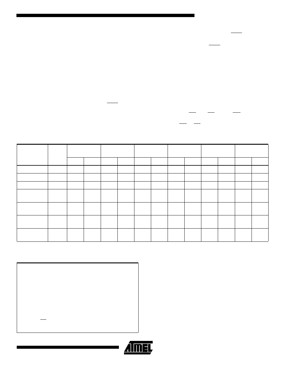
Notes:
1. The 8K byte boot sector has the address range 0000H to 1FFFH.
2. Either one of the Product ID exit commands can be used.
Command Definition (in Hex)
Command
Sequence
Bus
Cycles
1st Bus
Cycle
2nd Bus
Cycle
3rd Bus
Cycle
4th Bus
Cycle
5th Bus
Cycle
6th Bus
Cycle
Addr
Data
Addr
Data
Addr
Data
Addr
Data
Addr
Data
Addr
Data
Read
1
Addr
D
OUT
Chip Erase
6
5555
AA
2AAA
55
5555
80
5555
AA
2AAA
55
5555
10
Byte Program
4
5555
AA
2AAA
55
5555
A0
Addr
D
IN
Boot Block
Lockout
6
5555
AA
2AAA
55
5555
80
5555
AA
2AAA
55
5555
40
Product ID
Entry
3
5555
AA
2AAA
55
5555
90
Product ID
Exit
3
5555
AA
2AAA
55
5555
F0
Product ID
Exit
1
XXXX
F0
Absolute Maximum Ratings*
Temperature Under Bias ................................ -55
°
C to +125
°
C
*NOTICE:
Stresses beyond those listed under “Absolute
Maximum Ratings” may cause permanent dam-
age to the device. This is a stress rating only and
functional operation of the device at these or any
other conditions beyond those indicated in the
operational sections of this specification is not
implied. Exposure to absolute maximum rating
conditions for extended periods may affect device
reliability.
Storage Temperature ..................................... -65
°
C to +150
°
C
All Input Voltages
(including NC pins)
with Respect to Ground ...................................-0.6V to +6.25V
All Output Voltages
with Respect to Ground .............................-0.6V to V
CC
+ 0.6V
Voltage on OE
with Respect to Ground ...................................-0.6V to +13.5V