Timer/counters, The timer/counter0 prescaler, The timer/counter1 prescaler – Rainbow Electronics ATtiny15L User Manual
Page 25: Attiny15l
25
ATtiny15L
1187E–AVR–06/02
Timer/Counters
The ATtiny15L provides two general purpose 8-bit Timer/Counters. The Timer/Counters
h a ve s e p a ra te p r e s c a l i n g s e l e c ti o n f r o m s e p a ra te 1 0 - b i t p r e s c a l e r s . T h e
Timer/Counter0 uses internal clock (CK) as the clock time base. The Timer/Counter1
may use either the internal clock (CK) or the fast peripheral clock (PCK) as the clock
time base.
The Timer/Counter0
Prescaler
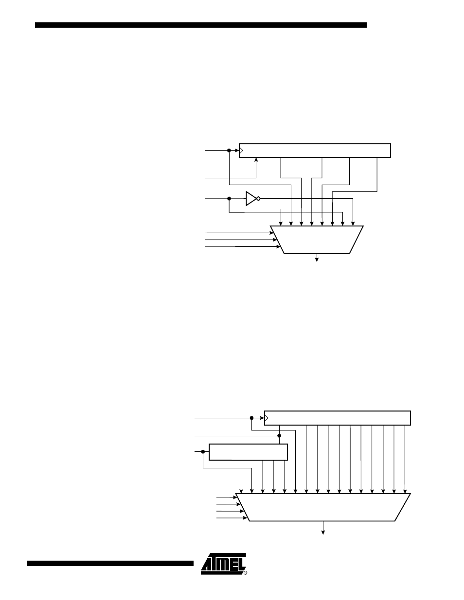
Figure 18 shows the Timer/Counter prescaler.
Figure 18. Timer/Counter0 Prescaler
The four prescaled selections are: CK/8, CK/64, CK/256, and CK/1024, where CK is the
Oscillator clock. CK, external source and stop, can also be selected as clock sources.
Setting the PSR10 bit in SFIOR resets the prescaler. This allows the user to operate
with a predictable prescaler.
The Timer/Counter1
Prescaler
Figure 19 shows the Timer/Counter1 prescaler. For Timer/Counter1 the clock selections
are: PCK, PCK/2, PCK/4, PCK/8, CK (=PCK/16), CK/2, CK/4, CK/8,CK/16, CK/32,
CK/64, CK/128, CK/256, CK/512, CK/1024, and stop. The clock options are described in
Table 12 on page 31 and the Timer/Counter1 Control Register (TCCR1). Setting the
PSR1 bit in the SFIOR Register resets the 10-bit prescaler. This allows the user to oper-
ate with a predictable prescaler.
Figure 19. Timer/Counter1 Prescaler
10-BIT T/C PRESCALER
0
TIMER/COUNTER0 CLOCK SOURCE
CK
T0
PSR0
CLEAR
CS00
TCK0
CS01
CS02
CK/8
CK/256
CK/1024
CK/64
10-BIT T/C PRESCALER
TIMER/COUNTER1 CLOCK SOURCE
CK
PSR1
CS10
CS11
CS12
CK/8
CK/256
CK/1024
CK/64
PCK
(25.6 MHz)
(1.6 MHz)
0
CS13
CLEAR
CLEAR
3-BIT T/C PRESCALER
PCK/2
PCK/4
PCK/8
CK (=PCK/16)
CK/2
CK/4
CK/16
CK/32
CK/128
CK/512