Ata6823 [preliminary, Application, Functional description – Rainbow Electronics ATA6823 User Manual
Page 5: 1 general remark, 1 power supply unit with supervisor functions
5
4856E–AUTO–07/07
ATA6823 [Preliminary]
4.
Application
4.1
General Remark
This chapter describes the principal application for which the ATA6823 was designed. Because
Atmel cannot be considered to understand fully all aspects of the system, application and envi-
ronment, no warranties of fitness for a particular purpose are given.
5.
Functional Description
5.1
Power Supply Unit with Supervisor Functions
5.1.1
Power Supply
The IC is supplied by a reverse-protected battery voltage. To prevent it from destruction, proper
external protection circuitry has to be added. It is recommended to use at least a capacitor com-
bination of storage and HF caps behind the reverse protection circuitry and closed to the VBAT
pin of the IC (see
A fully-internal low-power and low-drop regulator, stabilized by an external blocking capacitor
provides the necessary low-voltage supply needed for the wake-up process. The low-power
band gap reference is trimmed and is used for the bigger VCC regulator, too. All internal blocks
are supplied by the internal regulator.
Note:
The internal supply voltage V
INT
must not be used for any other supply purpose!
Nothing inside the IC except the logic interface to the microcontroller is supplied by the 5V/3.3V
VCC regulator.
A power-good comparator checks the output voltage of the V
INT
regulator and keeps the whole
chip in reset as long as the voltage is too low.
There is a high-voltage switch which brings out the battery voltage to the pin VBATSW for mea-
surement purposes. This switch is switched ON for VCC = HIGH and stays ON in case of a
watchdog reset going to sleep mode, VBATSW turns OFF. The signal can be used to switch on
external voltage regulators, etc.
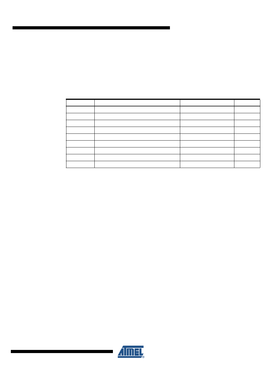
Table 4-1.
Typical External Components
Component Function
Value
Tolerance
C
VINT
Blocking capacitor at VINT
220 nF, 10V, X7R
10%
C
VCC
Blocking capacitor at VCC
2.2 µF, 10V, X7R
10%
C
CC
Cross conduction time definition capacitor
Typical 330 pF, 100V, COG
R
CC
Cross conduction time definition resistor
Typical 10 k
Ω
C
VG
Blocking capacitor at VG
470 nF, 25V, X7R
10%
C
CP
Charge pump capacitor
220 nF, 25V, X7R
10%
C
VRES
Reservoir capacitor
470 nF, 25V, X7R
10%
R
RWD
Watchdog time definition resistor
Typical 51 k
Ω
1%
C
LIN
Filter capacitor for LIN bus
Typical 220 pF, 100V
10%