Ata6823 [preliminary, Thermal resistance, Operating range – Rainbow Electronics ATA6823 User Manual
Page 16
16
4856E–AUTO–07/07
ATA6823 [Preliminary]
7.
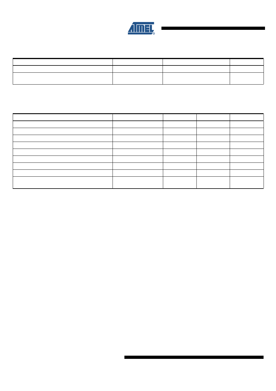
Thermal Resistance
Parameters
Symbol
Value
Unit
Thermal resistance junction to heat slug
R
thjc
< 5
K/W
Thermal resistance junction to ambient when heat
slug is soldered to PCB
R
thja
25
K/W
8.
Operating Range
The operating conditions define the limits for functional operation and parametric characteristics of the device. Functionality outside these
limits is not implied unless otherwise stated explicitly.
Parameters
Symbol
Min
Max
Unit
Operating supply voltage
(1)
V
VBAT1
7
18
V
Operating supply voltage
(2)
V
VBAT2
6
< 7
V
Operating supply voltage
(3)
V
VBAT3
3
< 6
V
Operating supply voltage
(4)
V
VBAT4
0
< 3
V
Operating supply voltage
(5)
V
VBAT5
> 20
40
V
Ambient temperature range under bias
T
a
–40
+125
°C
Normal functionality
T
a
–40
+125
°C
Normal functionality, overtemperature warning
T
a
150
165
°C
Drivers for H1, H2, L1, L2, and LIN are switched
OFF, VCC regulator is OFF
T
a
165
180
°C
Note:
1. Full functionality
2. H-bridge drivers may be switched off (undervoltage detection)
3. H-bridge drivers are switched off, 5V/3.3V regulator with reduced parameters, RESET works correctly
4. H-bridge drivers are switched off, 5V regulator not working, RESET not correct
5. H-bridge drivers are switched off