Rc2100 – Rainbow Electronics RC2100 User Manual
Page 5
RC2100
2005 Radiocrafts AS
RC2100 Data Sheet (rev. 1.0)
Page 5 of 22
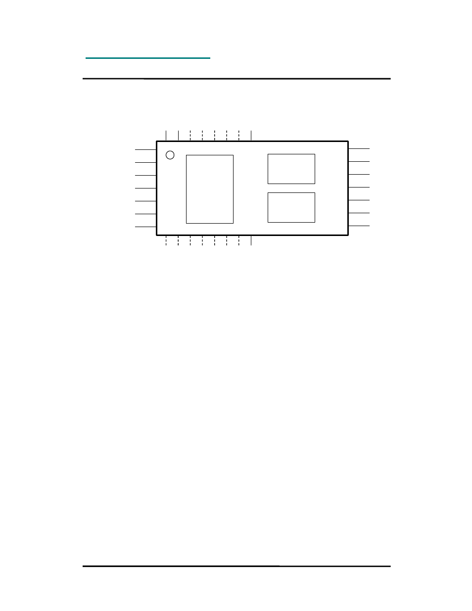
Block Diagram
GND
CTS/RXEN/RXTX
RTS/TXEN
CONFIG
TXD
RXD
GND
GND
VCC
ON/OFF
VDD
GND
RF
GND
1
2
3
4
5
6
7
14
13
12
11
10
9
8
15 16 17 18 19 20 21 22
30 29 28 27 26 25 24 23
SD
A
SC
L
C
C
A
/P
A
_E
N
Communication
controller
DSSS
RF Transceiver
Voltage
regulator
R
ES
ET
Circuit Description
The module contains a communication controller with embedded RC232™ protocol software,
a Direct Sequence Spread Spectrum high performance RF transceiver and an internal voltage
regulator.
The communication controller handles the radio packet protocol, the UART interface, the
synchronous interface, and controls the RF transceiver. Data to be sent by the host is
received at the RXD pin and buffered in the communication controller. The data packet is then
assembled with preamble, start-of-frame delimited (SOF), address information, Cyclic
Redundancy Check sum (CRC) and Frame Check Sequence (FCS) before it is transmitted on
RF. The preamble, SOF and FCS are always used. The address and CRC are optional.
The RF transceiver modulates the data to be transmitted on RF frequency, and demodulates
data that are received. Spread spectrum technology is used to enhance communication
reliability.
Received data are checked for correct address and CRC by the communication controller. If
the address matches the modules own address, and no CRC errors were detected, the data
packet is sent to the host on the TXD line after removing the header.
The asynchronous UART interface consists of RXD and TXD. Optionally CTS/RXTX and RTS
can be used for hardware handshake flow control. CTS/RXTX can be used to control the
direction of an RS485 driver circuit.
The module can also be used in an un-buffered transparent mode for data streaming. In this
case the data interface is synchronous using SCL and SDA for data transfer to/from the host.
The RXEN and TXEN are then used to set the operational mode.
When the CONFIG pin is asserted the communication controller enters configuration mode
and interprets data received on the RXD pin as configuration commands. There are
commands to change the radio channel, the output power, the destination address etc.
Permanent changes of the configuration is also possible and are then stored in internal non-
volatile memory (EEPROM).