Electrical characteristics (continued) – Rainbow Electronics MAX8775 User Manual
Page 3
MAX8775
Dual and Combinable Graphics Core
Controller for Notebook Computers
_______________________________________________________________________________________
3
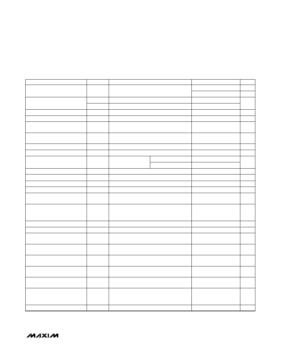
ELECTRICAL CHARACTERISTICS (continued)
(Circuit of Figure 1, V
IN
= 12V,
SKIP_ = PGND = AGND, ON_ = V
CC
= 5V, separate mode, T
A
= 0°C to +85°C, unless otherwise
noted. Typical values are at T
A
= +25°C.)
PARAMETER
SYMBOL
CONDITIONS
MIN
TYP
MAX
UNITS
50
%
SMPS1 to SMPS2 Phase Shift
SMPS2 starts after SMPS1
180
Deg
I
SLEW_
During transition
4.0
4.75
5.5
Slew-Rate Current
I
SLEWSS_
Startup and shutdown
0.70
0.95
1.20
µA
CURRENT LIMIT
Current-Limit Threshold
V
LIMIT
V
CSH
_ - V
CSL
_ 26
30
34
mV
Current-Limit Threshold
(Negative)
V
NEG
V
CSH
_ - V
CSL
_ ,
SKIP_ = V
CC
-43
-36
-29
mV
Current-Limit Threshold
(Zero Crossing)
V
ZX
V
CSH
_ - V
CSL
_ ,
SKIP_ = GND
3
mV
Idle Mode™ Threshold
I
MIN
V
CSH
_ - V
CSL
_ ,
SKIP_ = GND
3.6
6
8.4
mV
REFERENCE (REF)
T
A
= +25°C to +85°C
2.482
2.50
2.518
Reference Voltage
V
REF
V
CC
= 4.5V to 5.5V,
I
REF
= 0
T
A
= 0°C to +85°C
2.475
2.50
2.525
V
Refer ence S our ce Load Reg ul ati on
ΔV
REF
I
REF
= 0µA to 250µA
0.25
1.5
mV
Reference Sink Load Regulation
I
REF
= -50µA
6
mV
REF Lockout Voltage
V
R E F ( U V L O)
Rising edge, hysteresis = 100mV
2.3
V
CURRENT BALANCE
Current-Balance Amplifier (GMI)
Offset
[V(CSH1,CSL1) - V(CSH2,CSL2)] at I
CCI
= 0
-2
+2
mV
Current-Balance Amplifier (GMI)
Transconductance
ΔI
CCI
/
Δ[V(CSH1,CSL1) - V(CSH2,CSL2)],
V
CCI
= V
OUT
= 0.5V to 2.5V, and
V(CSH_,CSL_) = -60.0mV to +60.0mV
200
µS
FAULT DETECTION
OVP_ Adjust Range
V
OVP_
0.5
2.5
V
Outp ut Over vol tag e Tr i p Thr eshol d
Rising edge measured at CSL_,
with respect to OVP_ set voltage
180
200
220
mV
Output Overvoltage Fault
Propagation Delay
t
OVP
50mV overdrive
10
µs
Output Undervoltage Protection
Trip Threshold
Falling edge measured at CSL_,
with respect to error comparator threshold
-325
300
-275
mV
Output Undevoltage Fault
Propagation Delay
t
UVP
50mV overdrive
10
µs
Output Undervoltage Protection
Blanking Time
t
BLANK
From rising edge of ON_
6144
1/f
SW
PGOOD_ Lower Trip Threshold
Falling edge measured at CSL_,
with respect to error comparator threshold,
hysteresis = 1%
-180
-150
-120
mV
PGOOD_ Propagation Delay
t
PGOOD
_
Falling edge, 50mV overdrive
10
µs
Idle Mode is a trademark of Maxim Integrated Products, Inc.