Max8775, Setting the current limit – Rainbow Electronics MAX8775 User Manual
Page 24
MAX8775
mode. The amount of overshoot during a full-load to no-
load transient due to stored inductor energy can be cal-
culated as:
where N
PH
is 2 in combined mode when both phases
are active.
Setting the Current Limit
The minimum current-limit threshold must be great
enough to support the maximum load current when the
current limit is at the minimum tolerance value. The per-
phase peak inductor current occurs at I
LOAD(MAX)
plus
half the ripple current; therefore:
where N
PH
is 2 in combined mode, and I
LIMIT
equals the
minimum current-limit threshold voltage divided by the
current-sense resistance (R
SENSE_
). For the 30mV default
setting, the minimum current-limit threshold is 26mV.
The current-sense method (Figure 10) and magnitude
determine the achievable current-limit accuracy and
power loss. The sense resistor can be determined by:
R
SENSE_
= V
LIM_
/ I
LIMIT_
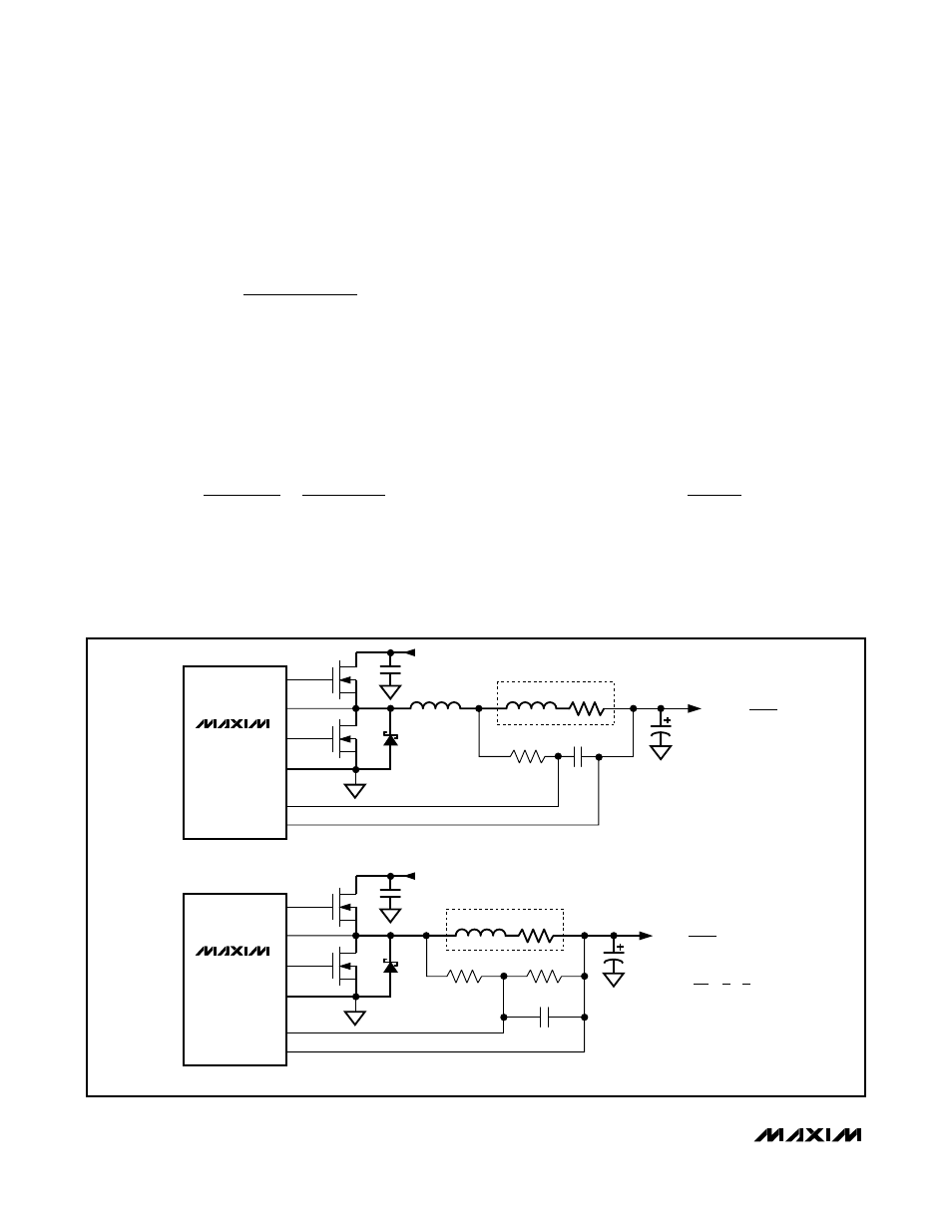
For the best current-sense accuracy and overcurrent
protection, use a 1% tolerance current-sense resistor
between the inductor and output as shown in Figure 10a.
This configuration constantly monitors the inductor cur-
rent, allowing accurate current-limit protection. However,
the parasitic inductance of the current-sense resistor can
cause current-limit inaccuracies, especially when using
low-value inductors and current-sense resistors. This
parasitic inductance (L
ESL
) can be cancelled by adding
an RC circuit across the sense resistor with an equivalent
time constant:
Alternatively, low-cost applications that do not require
highly accurate current-limit protection may reduce the
overall power dissipation by connecting a series RC
circuit across the inductor (Figure 10b) with an equiva-
lent time constant:
C
R
L
R
EQ EQ
ESL
SENSE
=
I
I
N
I
LIMIT
LOAD MAX
PH
INDUCTOR
>
+ ⎛
⎝⎜
⎞
⎠⎟
(
)
Δ
2
V
I
L
N
C
V
SOAR
LOAD MAX
PH OUT OUT
≈
(
)
Δ
(
)
2
2
Dual and Combinable Graphics Core
Controller for Notebook Computers
24
______________________________________________________________________________________
SENSE RESISTOR
L
MAX8775
C
OUT
INPUT (V
IN
)
C
IN
CSL_
CSH_
PGND
DL_
DH_
LX_
C
EQ
R
EQ
N
H
N
L
D
L
L
ESL
R
SENSE
C
EQ
R
EQ
=
L
ESL
R
SENSE
MAX8775
C
OUT
INPUT (V
IN
)
C
IN
b) LOSSLESS INDUCTOR SENSING
CSL_
CSH_
PGND
DL_
DH_
LX_
C
EQ
R
1
R
2
N
H
N
L
D
L
L
INDUCTOR
a) OUTPUT SERIES RESISTOR SENSING
R
DCR
R
CS
=
R2
= R
DCR
R1 + R2
R
DCR
=
L
[
1 + 1
]
C
EQ
R1 R2
Figure 10. Current-Sense Configurations