Pin description (continued) – Rainbow Electronics MAX8775 User Manual
Page 11
MAX8775
Dual and Combinable Graphics Core
Controller for Notebook Computers
______________________________________________________________________________________
11
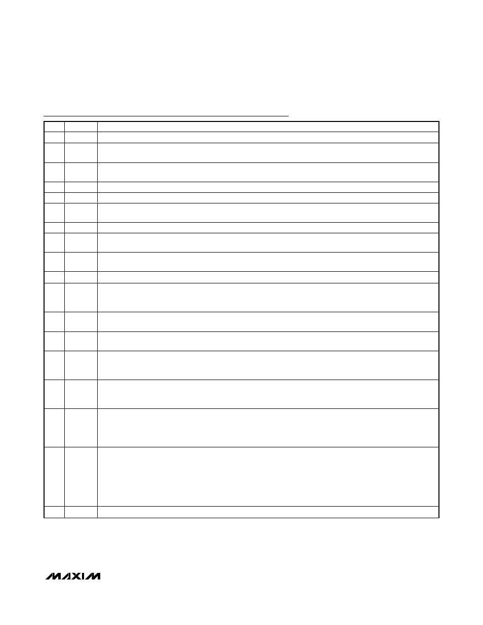
Pin Description (continued)
PIN
NAME
FUNCTION
16
DH2
High-Side Gate-Driver Output for SMPS2. DH2 swings from LX2 to BST2.
17
BST2
Boost Flying-Capacitor Connection for SMPS2. Connect to an external capacitor as shown in Figure 1. An optional
resistor in series with BST2 allows the DH2 turn-on current to be adjusted.
18
LX2
Inductor Connection for SMPS2. Connect LX2 to the switched side of the inductor. LX2 is the lower supply rail for
the DH2 high-side gate driver.
19
DL2
Low-Side Gate-Driver Output for SMPS2. DL2 swings from PGND to V
DD.
20
PGND
Power Ground
21
V
DD
Supply Voltage Input for the DL_ Gate Drivers. Connect to a 5V supply. Bypass V
DD
to AGND with a 1µF or
greater ceramic capacitor.
22
DL1
Low-Side Gate-Driver Output for SMPS1. DL1 swings from PGND to V
DD
.
23
LX1
Inductor Connection for SMPS1. Connect LX1 to the switched side of the inductor. LX1 is the lower supply rail for
the DH1 high-side gate driver.
24
BST1
Boost Flying-Capacitor Connection for SMPS1. Connect to an external capacitor as shown in Figure 1. An optional
resistor in series with BST1 allows the DH1 turn-on current to be adjusted.
25
DH1
High-Side Gate-Driver Output for SMPS1. DH1 swings from LX1 to BST1.
26
ON1
SMPS1 Enable Input. Drive ON1 high to enable SMPS1. Drive ON1 low to shut down SMPS1.
When both outputs are combined, ON1 is the master control signal to enable/disable the combined output, while
ON2 enables/disables phase 2, allowing 1- or 2-phase operation.
27
CSL1
Negative Current-Sense and Feedback Input for SMPS1. Connect to the negative terminal of the current-sense
element. CSL1 regulates to REFIN1. Figure 10 describes two different current-sensing options.
28
CSH1
Positive Current-Sense Input for SMPS1. Connect to the positive terminal of the current-sense element. Figure 10
describes two different current-sensing options.
29
SKIP1
Low-Noise Mode Control for SMPS1. Connect
SKIP1 to GND for normal Idle Mode (pulse-skipping) operation or to
V
CC
for PWM mode (fixed frequency).
When both outputs are combined,
SKIP2 is ignored and SKIP1 sets the skip function for both SMPS1 and SMPS2.
30
P G OO D 1
SMPS1 Open-Drain Power-Good Output. PGOOD1 is low when SMPS1 is more than 150mV below its regulation
threshold, when a 0V fault occurs, during soft-start, and in shutdown.
PGOOD1 is the voltage-regulation fault indicator when operating in combined mode.
31
DTRANS
Forced-Downward Transient Disable Input. Connect
DTRANS to V
CC
to disable the forced-downward transition
detection feature when operating in pulse-skipping mode, allowing the output to fall at a rate determined by the
load current and total output capacitance.
Connect
DTRANS to AGND to enable the forced downward-transition detection feature.
32
SLEW1
SMPS1 Slew-Rate Control. Connect a capacitor from SLEW1 to AGND to set the SMPS1 slew rate:
Slew Rate (
ΔV
OUT1
/
Δt) = I
SLEW1
/ C
SLEW1
During startup and shutdown, SMPS1 ramps at 1/5 the programmed slew rate.
In combined mode, the slew rate is set by both SLEW1 and SLEW2. Connect SLEW1 and SLEW2 together in
combined mode:
Combined Slew Rate (
ΔV
OUT
/
Δt) = (I
SLEW1
+ I
SLEW2
) / (C
SLEW1
+ C
SLEW2
)
—
EP
Exposed Backside Pad. Connect the exposed backside pad to AGND.