Rainbow Electronics MAX8775 User Manual
Page 19
In combined-mode operation, since the load is shared
between two phases, the load current at which
PFM/PWM crossover occurs is twice that of each
phase’s crossover current.
The switching waveforms may appear noisy and asyn-
chronous when light loading causes pulse-skipping
operation, but this is a normal operating condition that
results in high light-load efficiency. Trade-offs in PFM
noise vs. light-load efficiency are made by varying the
inductance. Generally, low inductance produces a
broader efficiency vs. load curve, while higher values
result in higher full-load efficiency (assuming that the
coil resistance remains fixed) and less output voltage
ripple. Penalties for using higher inductor values
include larger physical size and degraded load-tran-
sient response (especially at low input-voltage levels).
Output Voltage
The MAX8775 regulates each output to the voltage set
at REFIN_ by sensing the CSL_ pin. Changing the volt-
age at REFIN_ allows the MAX8775 to be used in appli-
cations that require dynamic output voltage changes
between two or more set points. Figure 1 shows a
dynamically adjustable resistive voltage-divider net-
work at REFIN_. Using system control signals to drive
the gate(s) of small-signal MOSFETs, resistors can be
switched in and out of the REFIN_ resistor-divider,
dynamically changing the voltage at REFIN_. The main
output voltage is determined by the following equation:
where R
EQ
is the equivalent resistance between
REFIN_ and ground, and R
TOP
is the resistance
between REFIN_ and REF (see Figures 1 and 2).
In combined mode (REFIN2 = V
CC
), REFIN1 sets the
voltage of the combined output.
Internal Integrator
The MAX8775 includes an internal transconductance
amplifier that integrates the feedback voltage and pro-
vides fine adjustment to the regulation voltage, allowing
accurate DC output-voltage regulation regardless of
the output ripple voltage. When the inductor conducts
continuously, the MAX8775 regulates the peak of the
output ripple. The internal integrator corrects for errors
due to ESR ripple voltage, slope compensation, and
current-sense load regulation, maintaining high DC
accuracy throughout the full load range, including light-
load operation while in pulse-skipping mode.
Dynamic Output Voltages
The MAX8775 controller automatically detects upward
transitions of 25mV at REFIN_, enters forced-PWM
operation, and blanks the power-good thresholds until
20µs after the output reaches the new regulation target.
The MAX8775 slews the output up at a rate set by the
slew capacitor C
SLEW
_:
Slew Rate (ΔV
OUT_
/ Δt) = I
SLEW_
/ C
SLEW_
where I
SLEW_
is 4.75µA (typ), and C
SLEW_
is the
capacitor across the SLEW_ pin and AGND. A 470pF
capacitor programs a slew rate of approximately
10mV/µs.
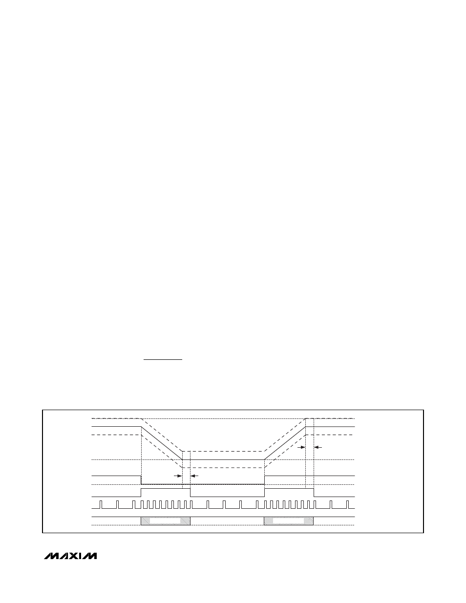
Setting
DTRANS low enables the automatic REFIN_
detection downward transitions (Figure 8). This feature
is especially useful as it allows the MAX8775 to be set
in the high-efficiency, pulse-skipping operation (
SKIP_
= low), while voltage transitions are automatically taken
care of by the MAX8775. Forced downward transitions
return the energy from the output capacitors back to
the input reservoir.
V
V
R
R
R
OUT PWM
REF
EQ
EQ
TOP
(
)
=
+
⎛
⎝⎜
⎞
⎠⎟
MAX8775
Dual and Combinable Graphics Core
Controller for Notebook Computers
______________________________________________________________________________________
19
V
OUT(HIGH)
V
OUT
V
OUT(LOW)
PGOOD THRESHOLD
OV THRESHOLD
REFIN
MODE
REFIN(HIGH)
REFIN(LOW)
TRACKING OV
20
μs
20
μs
FORCED-PWM
FORCED-PWM
DH
PULSE SKIP
PULSE SKIP
PULSE SKIP
PGOOD
BLANK HIGH-Z
BLANK HIGH-Z
Figure 8. REFIN Transition (Skip Mode, Downward Transition Enabled)