Max8775 – Rainbow Electronics MAX8775 User Manual
Page 18
MAX8775
When selecting a switching frequency, the minimum on-
time at the highest input voltage and lowest output voltage
must be greater than the 150ns (max) minimum on-time
specification in the
Electrical Characteristics
table:
V
OUT(MIN)
/ V
IN(MAX)
x T
SW
> t
ON(MIN)
A good rule is to choose a minimum on-time of at least
200ns.
When in pulse-skipping operation
SKIP_ = GND, the
minimum on-time must take into consideration the time
needed for proper skip-mode operation. The on-time
for a skip pulse must be greater than the 150ns (max)
minimum on-time specification in the
Electrical
Characteristics
table:
Forced-PWM Mode
To maintain low-noise, fixed-frequency operation, drive
SKIP_ high to put the output into forced-PWM mode.
This disables the zero crossing comparator and allows
negative inductor current. During forced-PWM mode,
the switching frequency remains constant and the no-
load supply current is typically between 20mA and
40mA per phase, depending on external MOSFETs and
switching frequency.
Light-Load Operation Control (
SKIP_)
The MAX8775 includes
SKIP_ inputs, which enable the
corresponding outputs to operate in discontinuous
mode. Connect
SKIP_ to GND to enable the zero-cross-
ing comparators of either controller. When the zero-
crossing comparator is enabled, the controller forces
DL_ low when the current-sense inputs detect zero
inductor current. This keeps the inductor from discharg-
ing the output capacitors and forces the controller to
skip pulses under light-load conditions to avoid over-
charging the output. During skip mode, the V
DD
current
consumption is reduced and efficiency is improved.
In combined mode,
SKIP2 is unused, and SKIP1 sets the
operating mode for both phases. At very light loads, one-
phase and two-phase pulse-skipping operation have
about the same efficiency (see the Efficiency vs. Load
Current (V
OUT
=1.5V) graph in
Typical Operating
Characteristics
). Keeping the MAX8775 in two-phase skip
allows it to dynamically respond to a full-load transient
without requiring any system level-control signal to indi-
cate the state of the GPU core.
Idle Mode Current-Sense Threshold
When pulse-skipping mode is enabled, the on-time of
the step-down controller terminates when the output
voltage exceeds the feedback threshold and when the
current-sense voltage exceeds the Idle Mode current-
sense threshold. Under light-load conditions, the on-
time duration depends solely on the Idle Mode
current-sense threshold, which is 20% (
SKIP_ = GND)
of the full load current-limit threshold. This forces the
controller to source a minimum amount of power with
each cycle. To avoid overcharging the output, another
on-time cannot begin until the output voltage drops
below the feedback threshold. Since the zero-crossing
comparator prevents the switching regulator from sink-
ing current, the controller must skip pulses. Therefore,
the controller regulates the valley of the output ripple
under light-load conditions.
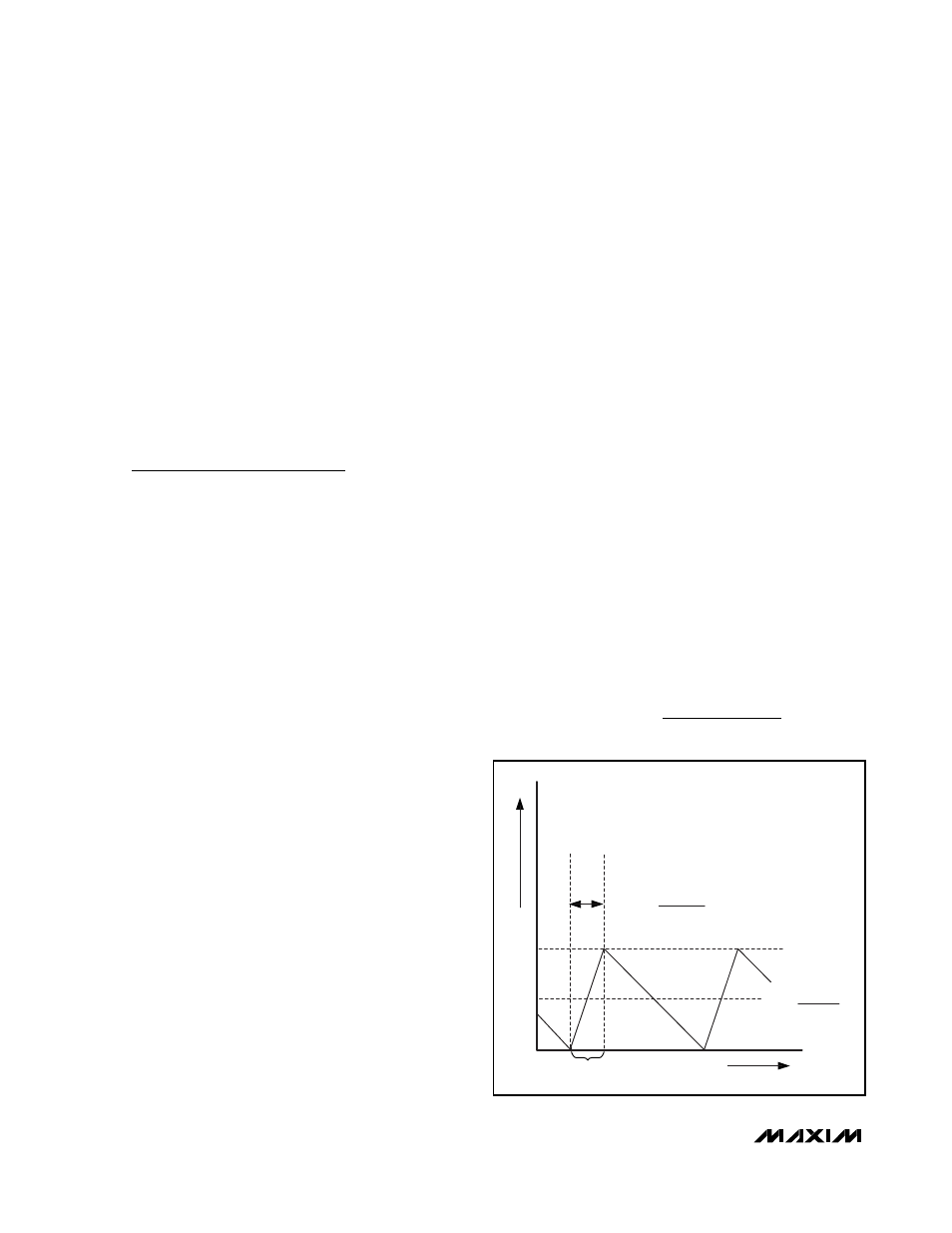
Automatic Pulse-Skipping Crossover
In skip mode, an inherent automatic switchover to PFM
takes place at light loads (Figure 7). This switchover is
affected by a comparator that truncates the low-side
switch on-time at the inductor current’s zero crossing.
The zero-crossing comparator senses the inductor cur-
rent across CSH_ and CSL_. Once V
CSH_
- V
CSL
_ drops
below the 3mV zero-crossing, current-sense threshold,
the comparator forces DL_ low. This mechanism causes
the threshold between pulse-skipping PFM and nonskip-
ping PWM operation to coincide with the boundary
between continuous and discontinuous inductor-current
operation (also known as the “critical-conduction” point).
The load-current level at which PFM/PWM crossover
occurs, I
LOAD(SKIP)
, is determined by:
I
V
V
V
LV f
LOAD SKIP
IN
OUT
OUT
IN OSC
(
)
(
)
=
−
2
L V
R
V
V
t
IMIN
SENSE
IN MAX
OUT MIN
ON MIN
Ч
Ч
−
≥
(
)
(
)
(
)
(
)
Dual and Combinable Graphics Core
Controller for Notebook Computers
18
______________________________________________________________________________________
t
ON(SKIP)
=
V
OUT
V
IN
f
OSC
INDUCTOR CURRENT
I
LOAD(SKIP)
2
I
LOAD =
I
LOAD(SKIP)
TIME
ON-TIME
0
Figure 7. Pulse-Skipping/Discontinuous Crossover Point