Max8775, Table 4. operating modes truth table – Rainbow Electronics MAX8775 User Manual
Page 22
MAX8775
In combined mode (REFIN2 = V
CC
), PGOOD1 indi-
cates the output voltage is in regulation, while PGOOD2
indicates the currents between the two phases are in
balance. PGOOD2 is the output of a comparator that
monitors the voltage difference between CCI2 and REF.
Since CCI2 is the output of a transconductance amplifi-
er, even small current imbalance over a long time caus-
es CCI2 to go high or low, depending on the current
imbalance. Whenever CCI2 is 20% above or below REF
(CCI2 ≥ 3V or CCI2 ≤ 2V), PGOOD2 goes low, indicat-
ing the currents in the two phases are not balanced.
PGOOD2 is blanked high impedance during all transi-
tions detected at REFIN_ until 20µs after the output
reaches the regulation voltage.
Fault Protection
Output Overvoltage Protection
The MAX8775 includes an OVP_ pin that allows flexible
setting of the overvoltage fault threshold. The overvolt-
age threshold is 200mV (typ) above the voltage at the
OVP_ pin. This simplifies the configuration, allowing the
OVP_ pin to be directly connected to REFIN_, eliminating
the need for extra resistors to set the overvoltage level.
If the output voltage of either SMPS rises 200mV above
its nominal regulation voltage, the corresponding con-
troller sets its overvoltage fault latch, pulls PGOOD_
low, and forces DL_ high for the faulted side. The other
controller is not affected. If the condition that caused
the overvoltage persists (such as a shorted high-side
MOSFET), the battery fuse blows. Cycle V
CC
below 1V
or toggle both ON_ pins to clear the overvoltage fault
latch and restart the SMPS controller.
In combined mode (REFIN2 = V
CC
), OVP1 sets the
overvoltage fault threshold for the combined output,
while OVP2 is connected to REF when OVP is enabled,
and to V
CC
when OVP is disabled.
Output Undervoltage Protection
If the output voltage of either SMPS falls 300mV below
its regulation voltage, the corresponding controller sets
its undervoltage fault latch, pulls PGOOD_ low, and
begins soft-shutdown for the faulted side by pulsing
DL_. DH_ remains off during the soft-shutdown
sequence initiated by an undervoltage fault. The other
controller is not affected. After soft-shutdown has com-
pleted, the MAX8775 forces DL_ high and DH_ low.
Cycle V
CC
below 1V or toggle ON_ to clear the under-
voltage fault latch and restart the SMPS controller.
V
CC
POR and UVLO
Power-on reset (POR) occurs when V
CC
rises above
approximately 2V, resetting the fault latch and prepar-
ing the PWM for operation. V
CC
undervoltage-lockout
(UVLO) circuitry inhibits switching, forces PGOOD_
low, and forces the DL_ gate drivers low.
If V
CC
drops low enough to trip the UVLO comparator
while ON_ is high, the MAX8775 immediately forces
DH_ and DL_ low on both controllers. The output dis-
charges to 0V at a rate dependent on the load and the
total output capacitance. This prevents negative output
voltages, eliminating the need for a Schottky diode to
GND at the output.
Dual and Combinable Graphics Core
Controller for Notebook Computers
22
______________________________________________________________________________________
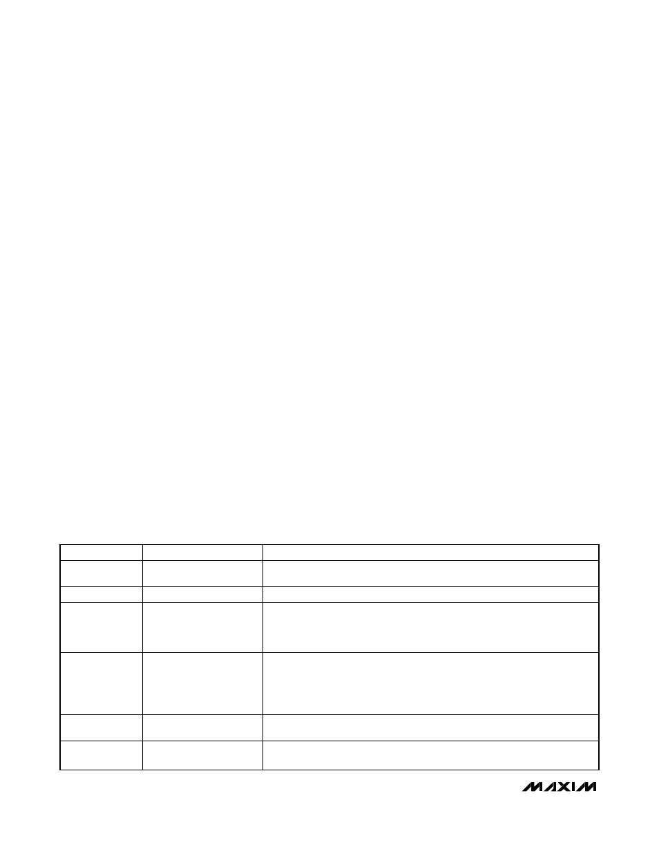
MODE
CONDITION
DESCRIPTION
Power-Up
V
CC
UVLO
When ON_ is high, DL_ is forced low as V
CC
falls below the 3.95V (typ) falling
UVLO threshold. DL_ is forced high when V
CC
falls below 1V (typ).
Run
ON1 or ON2 enabled
Normal operation.
Output
Overvoltage
Protection (OVP)
Either output > 200mV
above nominal level
When the overvoltage comparator trips, the faulted side sets the OV latch, forcing
PGOOD_ low and DL_ high. An OV fault on one SMPS does not affect the
operation of the other SMPS.
The O V l atch i s cl ear ed b y cycl i ng V
C C
b el ow 1V or cycl i ng b oth O N _ p i ns.
Output
Undervoltage
Protection (UVP)
Either output < 300mV
below nominal level, UVP is
enabled 6144 clock cycles
(1/f
OSC
) after the output is
enabled (ON_ going high)
When the undervoltage comparator trips, the faulted side sets the UV latch,
forcing PGOOD_ low and initiating the soft-shutdown sequence by pulsing only
DL_. DL_ goes low after soft-shutdown. A UV fault on one SMPS does not affect
the operation of the other SMPS.
The U V l atch i s cl ear ed b y cycl i ng V
C C
b el ow 1V or cycl i ng the r esp ecti ve O N _ p i n.
Shutdown
ON1 and ON2
are driven low
DL_ stays low after soft-shutdown is completed.
All circuitry is shut down.
Thermal
Shutdown
T
J
> +160°C
Exited by POR or cycling ON1 and ON2.
DL1 and DL2 remain low.
Table 4. Operating Modes Truth Table