Max8775, Table 3. dtrans operating modes truth table – Rainbow Electronics MAX8775 User Manual
Page 20
MAX8775
Setting
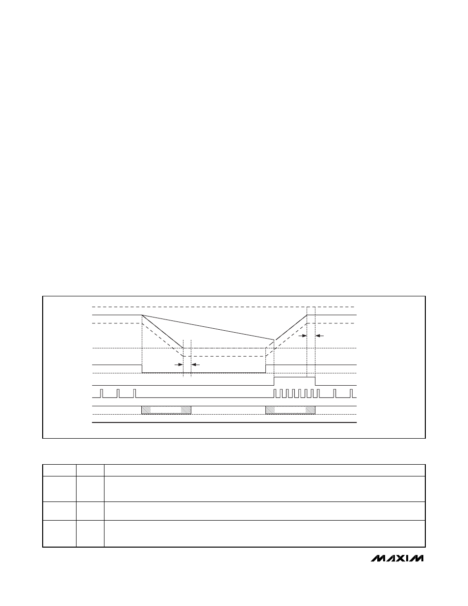
DTRANS high disables the forced downward
REFIN_ transition. This allows the output voltage to drift
down at a rate determined by the load current and the
total output capacitance (Figure 9). Downward transitions
in some systems are less critical from a timing standpoint
because the voltage is above the new lower target.
The power consumed in moving the output voltage to
the new lower level in a forced manner where the
energy is returned to the input with
DTRANS low,
needs to be weighed against the higher leakage
power loss when the voltage drifts down with
DTRANS
high. Since the efficiency calculations require com-
plex workload duty factors to be taken into considera-
tion, a simple setting of the
DTRANS pin allows
testing and comparison in both modes to determine
which mode offers best efficiency. Table 3 is the
DTRANS operating modes truth table.
Combined-Mode Operation
Combined Mode (REFIN2 = V
CC
)
Combined-mode operation allows the MAX8775 to sup-
port even higher output currents by sharing the load
current between two phases, distributing the power
dissipation over several power components. The
MAX8775 is configured in combined mode by connecting
REFIN2 to V
CC
and OVP2 to REF or V
CC
. See Figure 2
for the combined-mode standard application schematic.
See the OVP2 connection requirements in the
Pin
Description
table.
Phase Transition (ON2)
While in combined mode, ON1 functions as the master
control signal that enables/disables the combined out-
put. ON2 enables/disables only phase 2. This allows for
flexible power management where phase 2 can be dis-
abled at lighter loads, operating at the most optimal
point of the efficiency curve. The MAX8775 does not
override the ON2 signal during startup and shutdown. If
ON2 is low during startup and shutdown, the MAX8775
operates only in one phase. Since the startup and shut-
down slew rates are slow and the load currents are typi-
cally low, one-phase operation during startup and
shutdown might be possible. Actual system testing and
characterization of system load is required to guarantee
operation in this mode.
Dual and Combinable Graphics Core
Controller for Notebook Computers
20
______________________________________________________________________________________
TARGET
PGOOD THRESHOLD
FIXED OV THRESHOLD
REFIN
REFIN TRANSITION (SKIP MODE, DOWNWARD TRANSITION DISABLED)
MODE
REFIN(HIGH)
REFIN(LOW)
20
μs
20
μs
PWM MODE
DH
PULSE SKIP
PULSE SKIP
PGOOD
OUTPUT DRAGGED
DOWN BY LOAD
VOUT(HIGH)
VOUT(LOW)
BLANK HIGH-Z
BLANK HIGH-Z
Figure 9. REFIN Transition (Skip Mode, Downward Transition Disabled)
DTRANS
SKIP_
OPERATION DURING TRANSITION
X
H
SKIP_ sets the respective phase in forced-PWM mode.
All positive and negative REFIN transitions are forced. PGOOD_ is blanked during the SLEW_ capacitor
transition + 20µs.
H
L
SKIP_ sets the respective phase in pulse-skipping mode.
Negative REFIN transitions are not forced, and the output voltage is discharged by the load.
L
L
SKIP_ sets the respective phase in pulse-skipping mode.
All positive and negative REFIN transitions are forced. PGOOD_ is blanked during the SLEW_ capacitor
transition + 20µs.
Table 3.
DTRANS Operating Modes Truth Table