Max8775, Smps detailed description – Rainbow Electronics MAX8775 User Manual
Page 16
MAX8775
SMPS Detailed Description
SMPS Enable Controls (ON1, ON2)
ON1 and ON2 provide independent control of output
soft-start and soft-shutdown. This allows flexible control
of startup and shutdown sequencing. The outputs may
be started simultaneously, sequentially, or independent-
ly. To provide sequential startup, connect ON_ of one
regulator to PGOOD_ of the other. For example, with
ON1 connected to PGOOD2, OUT1 soft-starts after
OUT2 is in regulation. Additionally, tracking and ratio-
metric startup and shutdown can be achieved using the
SLEW_ capacitors. See the
Startup Sequencing
section.
When configured in combined mode (REFIN2 = V
CC
),
ON1 is the master control input that enables/disables
the combined output. ON2 enables/disables only the
2nd phase, allowing dynamic switching between one-
phase and two-phase operation.
Toggle ON_ low to clear the overvoltage, undervoltage,
and thermal-fault latches.
Soft-Start and Soft-Shutdown
Soft-start begins when ON_ is driven high and REF is in
regulation. During soft-start, the output is ramped up
from 0V to the final set voltage at 1/5 the slew rate pro-
grammed by the capacitor at the SLEW_ pin. This
reduces inrush current and provides a predictable
ramp-up time for power sequencing:
Soft-Start/Stop Slew Rate (ΔV
OUT_
/ Δt) =
I
SLEWSS_
/ C
SLEW_
where I
SLEWSS_
is 0.95µA (typ), and C
SLEW_
is the
capacitor across the SLEW_ pin and AGND. A 470pF
capacitor programs a slew rate of approximately
10mV/µs, and a soft-start, soft-shutdown slew rate of
approximately 2mV/µs.
Soft-shutdown begins after ON_ goes low, an output
undervoltage fault, or a thermal fault. During soft-shut-
down, the output is ramped down to 0V at 1/5 the pro-
grammed slew rate, reducing negative inductor
currents that can cause negative voltages on the out-
put. At the end of soft-shutdown, DL_ is driven high
until startup is again triggered by a rising edge of ON_.
The reference is turned off when both outputs have
been shut down.
When configured in separate mode, the two outputs are
independent. A fault at one output does not trigger
shutdown of the other.
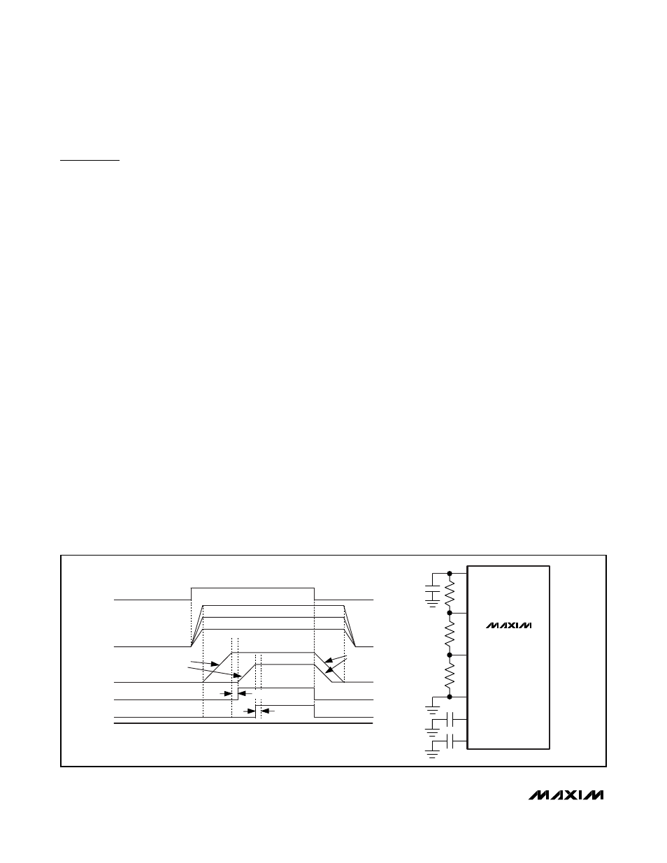
Startup Sequencing
Individually programmable slew-rate control, on/off con-
trol, and power-good outputs allow flexible configuration
of the MAX8775 for different power-up sequencing. This
is useful in applications where one power rail needs to
come up after another, track another rail, or reach regu-
lation at about the same time. Figures 4, 5, and 6 show
three configurations for startup sequencing.
Fixed-Frequency, Current-Mode PWM
Controller
The heart of each current-mode PWM controller is a
multi-input, open-loop comparator that sums three sig-
nals: the output voltage-error signal with respect to the
reference voltage, the current-sense signal, and the
slope compensation ramp (Figure 3). The MAX8775
uses a direct-summing configuration, approaching
ideal cycle-to-cycle control over the output voltage
Dual and Combinable Graphics Core
Controller for Notebook Computers
16
______________________________________________________________________________________
REF
REFIN2
PGOOD1 = ON2
ON1
REFIN1
V
OUT1
V
OUT2
PGOOD2
20
μs
DELAYED STARTUP/SHUTDOWN TIMING
REF
REFIN2
REFIN1
AGND
SLEW1
SLEW2
C
SLEW1
= C
SLEW2
C
REF
1/5 PROGRAMMED
SLEW RATE
1/5 PROGRAMMED
SLEW RATE
MAX8775
20
μs
Figure 4. MAX8775 Delayed Startup/Shutdown Timing