Rainbow Electronics MAX17047 User Manual
Simplified operating circuit, General description, Applications features
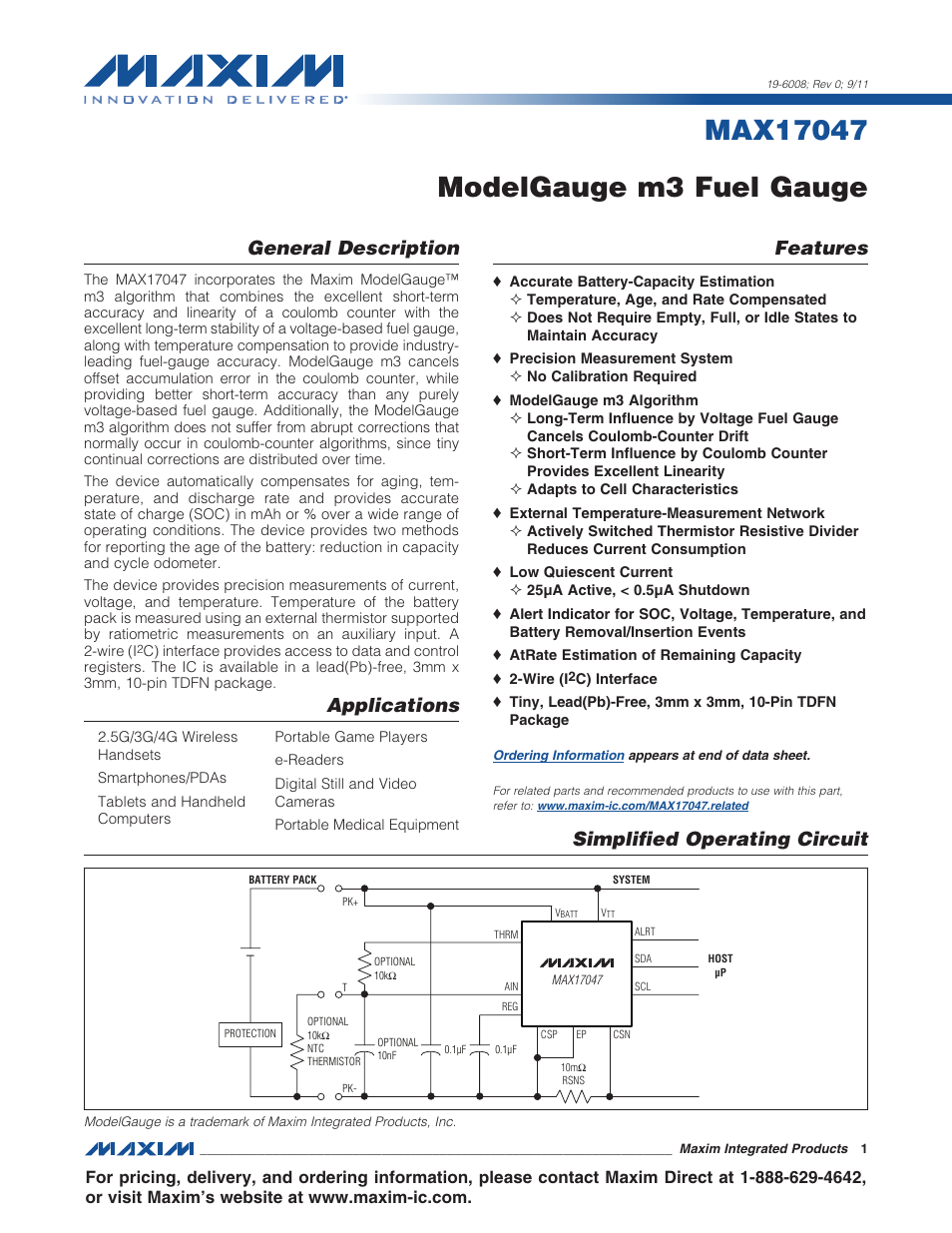
Table of contents
Document Outline
- General Description
- Applications
- Features
- Simplified Operating Circuit
- Absolute Maximum Ratings
- Electrical Characteristics
- Electrical Characteristics: 2-Wire Interface
- I2C Bus Timing Diagram
- Typical Operating Characteristics
- Typical Operating Characteristics
- Pin Configuration
- Pin Description
- Block Diagram
- Detailed Description
- ModelGauge m3 Algorithm
- Typical Operating Circuit
- Recommended Layout
- ModelGauge m3 Registers
- ModelGauge Algorithm Output Registers
- Application-Specific Registers
- End-of-Charge Detection
- Cell Characterization Information Registers
- Algorithm Configuration Registers
- Power-Up and Power-On Reset
- Battery Removal and Insertion
- Modes of Operation
- ALRT Function
- Status and Configuration
- Voltage Measurement
- Current Measurement
- Temperature Measurement
- IC Memory Map
- 2-Wire Bus System
- Ordering Information
- Package Information
- Revision History
- LIST OF FIGURES
- Figure 1. IC Bus Timing Diagram
- Figure 2. ModelGauge m3 Overview
- Figure 3. ModelGauge m3 OCV and Coulomb-
- Figure 4. ModelGauge m3 Algorithm Mixing
- Figure 5. Typical Operating Circuit
- Figure 6. Operating Circuits that Share
- Figure 7. Proper Board Layout
- Figure 8. ModelGauge m3 Register Map
- Figure 9. SOC Register Format (Output)
- Figure 10. RemCap Register Format (Outpu
- Figure 11. SOC Register Format (Output)
- Figure 12. RemCap Register Format (Outpu
- Figure 13. SOC Register Format (Output)
- Figure 14. RemCap Register Format (Outpu
- Figure 15. SOC Register Format (Output)
- Figure 16. TTE Register Format (Output)
- Figure 17. Age Register Format (Output)
- Figure 18. Cycles Register Format (Outpu
- Figure 19. VFOCV Register Format (Output
- Figure 20. FullCAP Register Format (Outp
- Figure 21. FullCapNom Register Format (O
- Figure 22. QH Register Format (Output)
- Figure 23. DesignCap Register Format (In
- Figure 24. FullSOCThr Register Format (I
- Figure 25. False End-of-Charge Events
- Figure 26. FullCAP Learning at End of Ch
- Figure 27. ICHGTerm Register Format (Inp
- Figure 28. V_empty Register Format (Inpu
- Figure 29. FilterCFG Register Format (In
- Figure 30. RelaxCFG Register Format (Inp
- Figure 31. Cell Relaxation Detection
- Figure 32. LearnCFG Register Format (Inp
- Figure 33. MiscCFG Register Format (Inpu
- Figure 34. FSTAT Register Format (Output
- Figure 35. AtRate Register Format (Input
- Figure 37. Operation After Cell Insertio
- Figure 38. Fast Detection of Cell Remova
- Figure 39. MAX17047 State Based on Shutd
- Figure 40. V Threshold Register Format (
- Figure 41. T Threshold Register Format (
- Figure 42. S Threshold Register Format (
- Figure 43. CONFIG Register Format (Input
- Figure 44. Timer Register Format (Output
- Figure 45. SHDNTIMER Register Format (In
- Figure 46. Status Register Format (Input
- Figure 47. Version Register Format (Outp
- Figure 48. V Register Format (Output)
- Figure 49. AverageV Register Format (Out
- Figure 50. MaxMinV Register Format (Outp
- Figure 51. Current Register Format (Outp
- Figure 52. AverageCurrent Register Forma
- Figure 53. MaxMinCurrent Register Format
- Figure 54. CGAIN Register Format (Input)
- Figure 55. COFF Register Format (Input)
- Figure 56. AIN Register Format (Output)
- Figure 57. Temperature Register Format (
- Figure 58. AverageTemperature Register F
- Figure 59. MaxMinTemperature Register Fo
- Figure 60. TGAIN Register Format (Input)
- Figure 61. TOFF Register Format (Input)
- LIST OF TABLES