Version register (21h), Voltage measurement, Vcell register (09h) – Rainbow Electronics MAX17047 User Manual
Page 35: Averagevcell register (19h), Maxminvcell register (1bh), Figure 47. version register format (outp, Figure 48. v register format (output), Figure 49. averagev register format (out
���������������������������������������������������������������� Maxim Integrated Products 35
MAX17047
ModelGauge m3 Fuel Gauge
Version Register (21h)
The Version register holds a 16-bit value that indicates
the version of the device.
register format.
Voltage Measurement
While in active mode, the device periodically measures
the voltage between the V
BATT
and CSP pins over a 2.5V
to 4.98V range. The resulting data is placed in the V
CELL
register every 175.8ms with an LSb value of 0.625mV.
Additionally, the device maintains a record of the mini-
mum and maximum voltage measured by the device,
and an average voltage over a time period defined by
the host. Contents of the V
CELL
and AverageV
CELL
registers are indeterminate for the first conversion cycle
time period after device power-up. The last values of the
V
CELL
and AverageV
CELL
registers are maintained when
the device enters shutdown mode.
V
CELL
Register (09h)
While in active mode, the device periodically measures the
voltage between the V
BATT
and CSP pins over a 0 to 4.98V
range. The resulting data is placed in the V
CELL
register
every 175.8ms with an LSb value of 0.625mV. Voltages
above the maximum register value are reported as the
maximum value. The lower 3 bits of the V
CELL
register are
don’t care bits.
CELL
register format.
AverageV
CELL
Register (19h)
The AverageV
CELL
register reports an average of V
CELL
register readings over a configurable 12s to 24min time
period. See the FilterCFG register description for details on
setting the time filter. The resulting average is placed in the
AverageV
CELL
register with an LSb value of 0.625mV. The
lower 3 bits of the AverageV
CELL
register are don’t care
bits.The first V
CELL
register reading after device power-
up sets the starting point of the AverageV
CELL
filter. Note
that when a cell relaxation event is detected, the averag-
ing period for the AverageV
CELL
register changes to the
period defined by dt3:dt0 in the RelaxCFG register. The
AverageV
CELL
register reverts back to its normal averag-
ing period when a charge or discharge current is detect-
ed.
shows the AverageV
CELL
register format.
MaxMinV
CELL
Register (1Bh)
The MaxMinV
CELL
register maintains the maximum and
minimum V
CELL
register values since the last fuel-gauge
reset or until reset by the host software. Each time the
V
CELL
register updates, it is compared against these
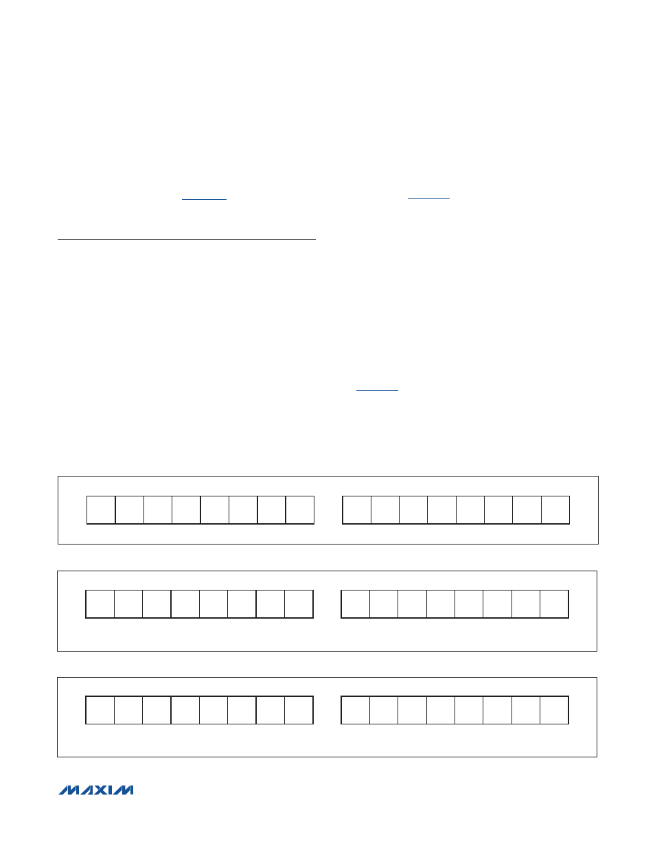
Figure 47. Version Register Format (Output)
Figure 48. V
CELL
Register Format (Output)
Figure 49. AverageV
CELL
Register Format (Output)
Figure 47
MSB—ADDRESS 21h
LSB—ADDRESS 21h
V
15
V
14
V
13
V
12
V
11
V
10
V
9
V
8
V
7
V
6
V
5
V
4
V
3
V
2
V
1
V
0
MSb
LSb
MSb
LSb
Figure 48
MSB—ADDRESS 09h
LSB—ADDRESS 09h
2
12
2
11
2
10
2
9
2
8
2
7
2
6
2
5
2
4
2
3
2
2
2
1
2
0
X
X
X
MSb
LSb
MSb
LSb
UNITS: 0.625mV
Figure 49
MSB—ADDRESS 19h
LSB—ADDRESS 19h
2
12
2
11
2
10
2
9
2
8
2
7
2
6
2
5
2
4
2
3
2
2
2
1
2
0
X
X
X
MSb
LSb
MSb
LSb
UNITS: 0.625mV