Modelgauge m3 registers, Figure 8. modelgauge m3 register map – Rainbow Electronics MAX17047 User Manual
Page 14
���������������������������������������������������������������� Maxim Integrated Products 14
MAX17047
ModelGauge m3 Fuel Gauge
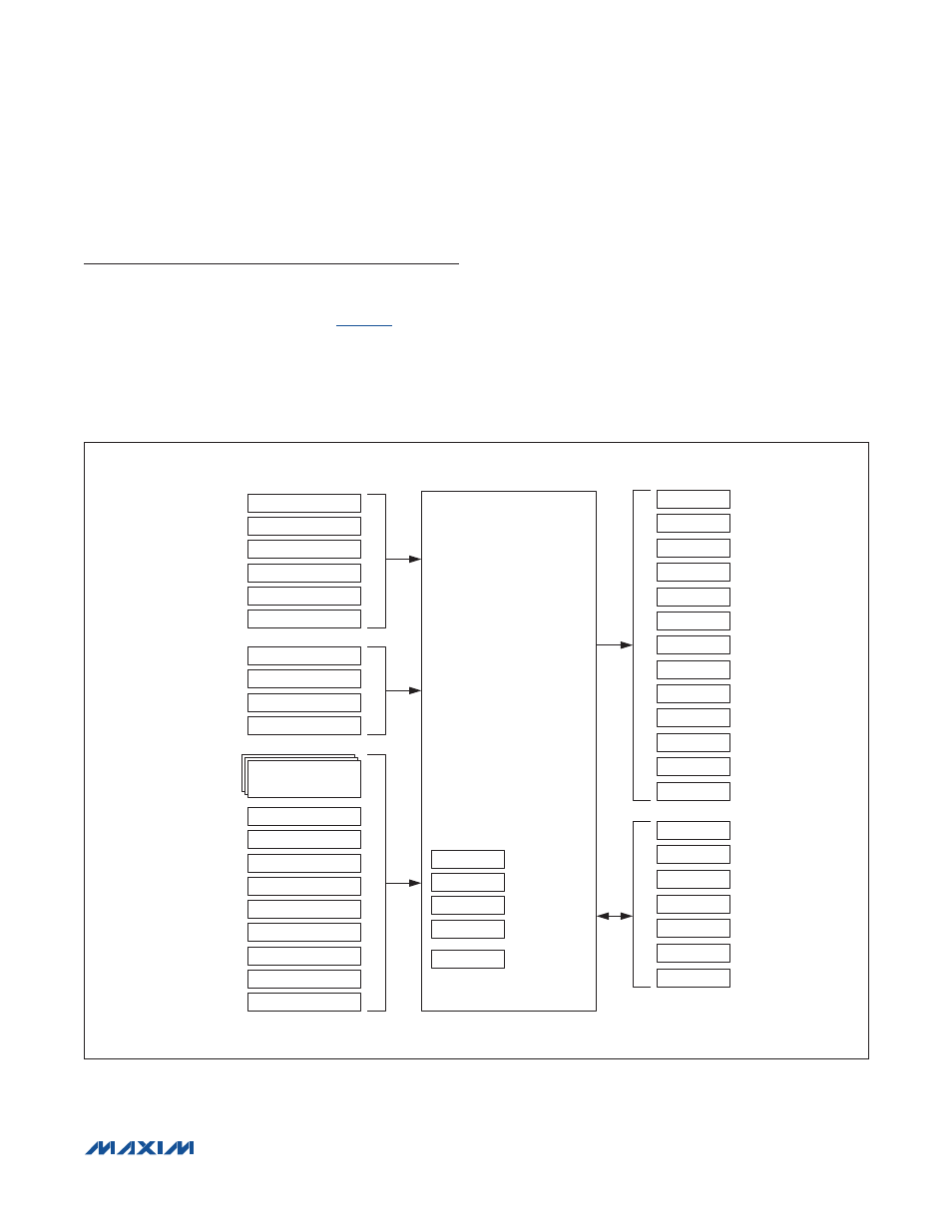
Figure 8. ModelGauge m3 Register Map
ModelGauge m3 Registers
To calculate accurate results, ModelGauge m3 requires
information about the cell, the application, and real-time
information measured by the device.
inputs and outputs to the algorithm grouped by category.
Analog input registers are the real-time measurements
of voltage, temperature, and current performed by the
device. Application-specific registers are programmed
by the customer to reflect the operation of the applica-
tion. The Cell Characterization Information registers
hold characterization data that models the behavior of
the cell over the operating range of the application. The
Algorithm Configuration registers allow the host to adjust
performance of the device for their application. The Save
and Restore registers allow an application to maintain
accuracy of the algorithm after the device has been
power cycled. The following sections describe each
register in detail.
ModelGauge ALGORITHM
V
CELL
CURRENT
TEMPERATURE
AverageV
CELL
AverageCurrent
AverageTemperature
FilterCFG
LearnCFG
RelaxCFG
MiscCFG
AtRate
ALGORITHM
CONFIGURATION
FullCapNom
Iavg_empty
CELL
CHARACTERIZATION
INFORMATION
RCOMP0
TempCo
TempNom
TempLim
V_empty
CHARACTERIZATION
TABLE
FCTC
QResidual Table
ANALOG
INPUTS
DesignCap
ICHGTerm
FullSOCThr
V_empty
APPLICATION
SPECIFIC
FullCAP
FullCapNom
FSTAT
RemCap
MIX
SOC
REP
RemCap
REP
SOC
AV
RemCap
AV
TTE
AGE
CYCLES
OCV
SOC
MIX
ModelGauge
ALGORITHM
OUTPUTS
CYCLES
RCOMP0
TempCo
dQacc
dPacc
FullCAP
SAVE AND
RESTORE
INFORMATION
QResidual Table