Status register (00h), Figure 46. status register format (input – Rainbow Electronics MAX17047 User Manual
Page 34
���������������������������������������������������������������� Maxim Integrated Products 34
MAX17047
ModelGauge m3 Fuel Gauge
THR2:THR0—Sets the shutdown timeout period from a
minimum of 45s to a maximum of 1.6h. The default POR
value of 7h gives a shutdown delay of 1.6h. The equation
setting the period is:
Shutdown Timeout Period = 175.8ms O 2
(8+THR)
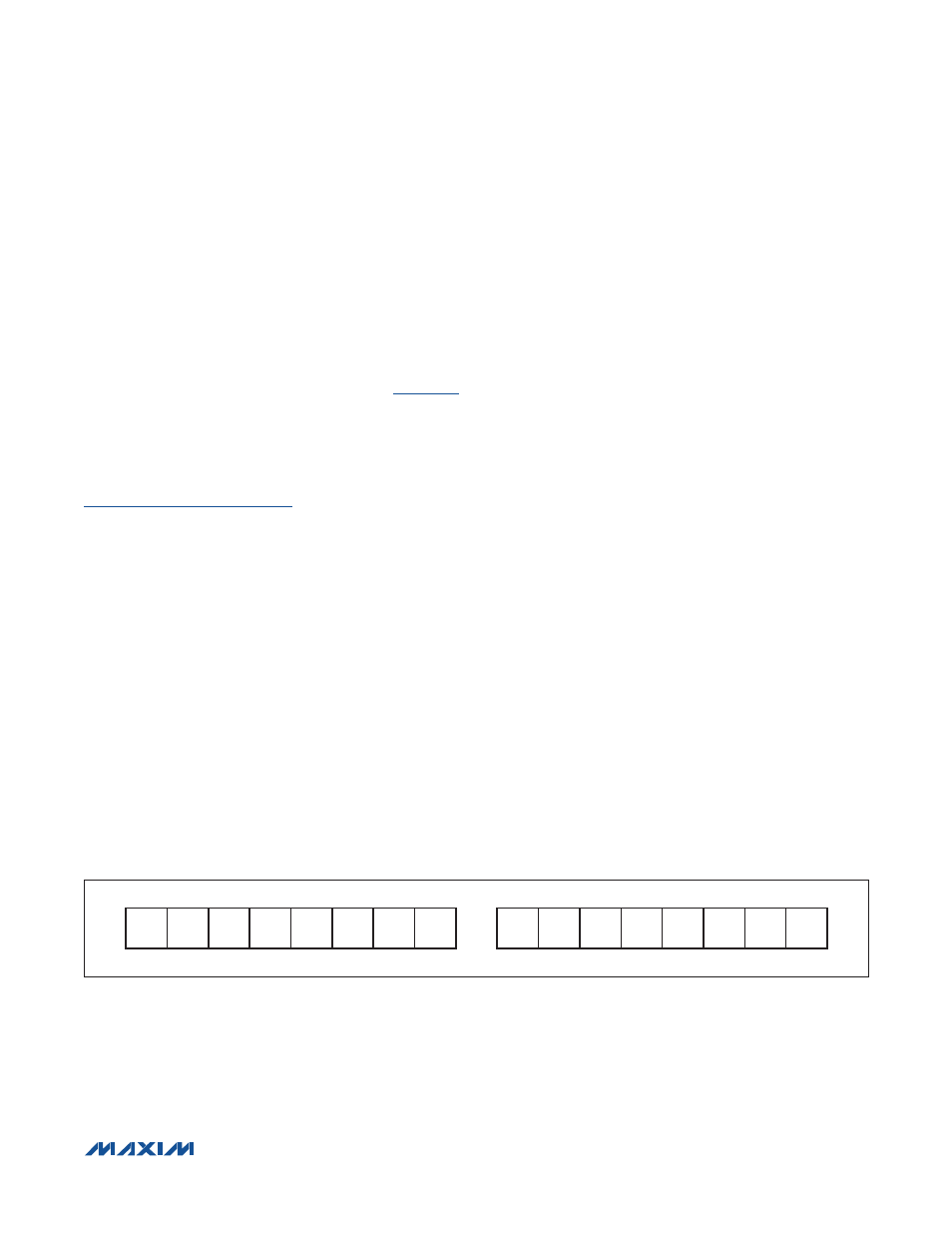
Status Register (00h)
The Status register maintains all flags related to alert
thresholds and battery insertion or removal.
shows the Status register format.
POR—Power-On Reset. This bit is set to a 1 when the
device detects that a software or hardware POR event
has occurred. If the host detects that the POR bit has
been set, the device should be reconfigured. See the
cleared by system software to detect the next POR event.
POR is set to 1 at power-up.
Bst—Battery Status. This bit is set to 0 when a battery
is present in the system and set to 1 when the battery is
removed. Bst is set to 0 at power-up.
Vmn—Minimum V
ALRT
Threshold Exceeded. This bit is
set to a 1 whenever a V
CELL
register reading is below
the minimum V
ALRT
value. This bit may or may not need
to be cleared by system software to detect the next
event. See V
S
in the CONFIG register. Vmn is set to 0 at
power-up.
Tmn—Minimum T
ALRT
Threshold Exceeded. This bit is
set to a 1 whenever a Temperature register reading is
below the minimum T
ALRT
value. This bit may or may not
need to be cleared by system software to detect the next
event. See T
S
in the CONFIG register. Tmn is set to 0 at
power-up.
Smn—Minimum SOC
ALRT
Threshold Exceeded. This
bit is set to a 1 whenever SOC falls below the minimum
SOC
ALRT
value. This bit may or may not need to be
cleared by system software to detect the next event. See
S
S
in the CONFIG register and SACFG in the MiscCFG
register. Smn is set to 0 at power-up.
Bi—Battery Insertion. This bit is set to a 1 when the
device detects that a battery has been inserted into
the system by monitoring the AIN pin. This bit must be
cleared by system software to detect the next insertion
event. Bi is set to 0 at power-up.
Vmx—Maximum V
ALRT
Threshold Exceeded. This bit is
set to a 1 whenever a V
CELL
register reading is above the
maximum V
ALRT
value. This bit may or may not need to be
cleared by system software to detect the next event. See
V
S
in the CONFIG register. Vmx is set to 0 at power-up.
Tmx—Maximum T
ALRT
Threshold Exceeded. This bit is
set to a 1 whenever a Temperature register reading is
above the maximum T
ALRT
value. This bit may or may
not need to be cleared by system software to detect the
next event. See T
S
in the CONFIG register. Tmx is set to
0 at power-up.
Smx—Maximum SOC
ALRT
Threshold Exceeded. This bit
is set to a 1 whenever SOC rises above the maximum
SOC
ALRT
value. This bit may or may not need to be
cleared by system software to detect the next event. See
S
S
in the CONFIG register and SACFG in the MiscCFG
register. Smx is set to 0 at power-up.
Br—Battery Removal. This bit is set to a 1 when the sys-
tem detects that a battery has been removed from the
system. This bit must be cleared by system software to
detect the next insertion event. Br is set to 0 at power-up.
X—Don’t Care. This bit is undefined and can be logic 0 or 1.
Figure 46. Status Register Format (Input/Output)
MSB—ADDRESS 00h
LSB—ADDRESS 00h
Br
Smx
Tmx
Vmx
Bi
Smn Tmn Vmn
X
X
X
X
Bst
X
POR
X
MSb
LSb
MSb
LSb
Figure 46