Salrt threshold register (03h), Status and configuration, Config register (1dh) – Rainbow Electronics MAX17047 User Manual
Page 32: Figure 42. s threshold register format, Figure 43. config register format (input
���������������������������������������������������������������� Maxim Integrated Products 32
MAX17047
ModelGauge m3 Fuel Gauge
S
ALRT
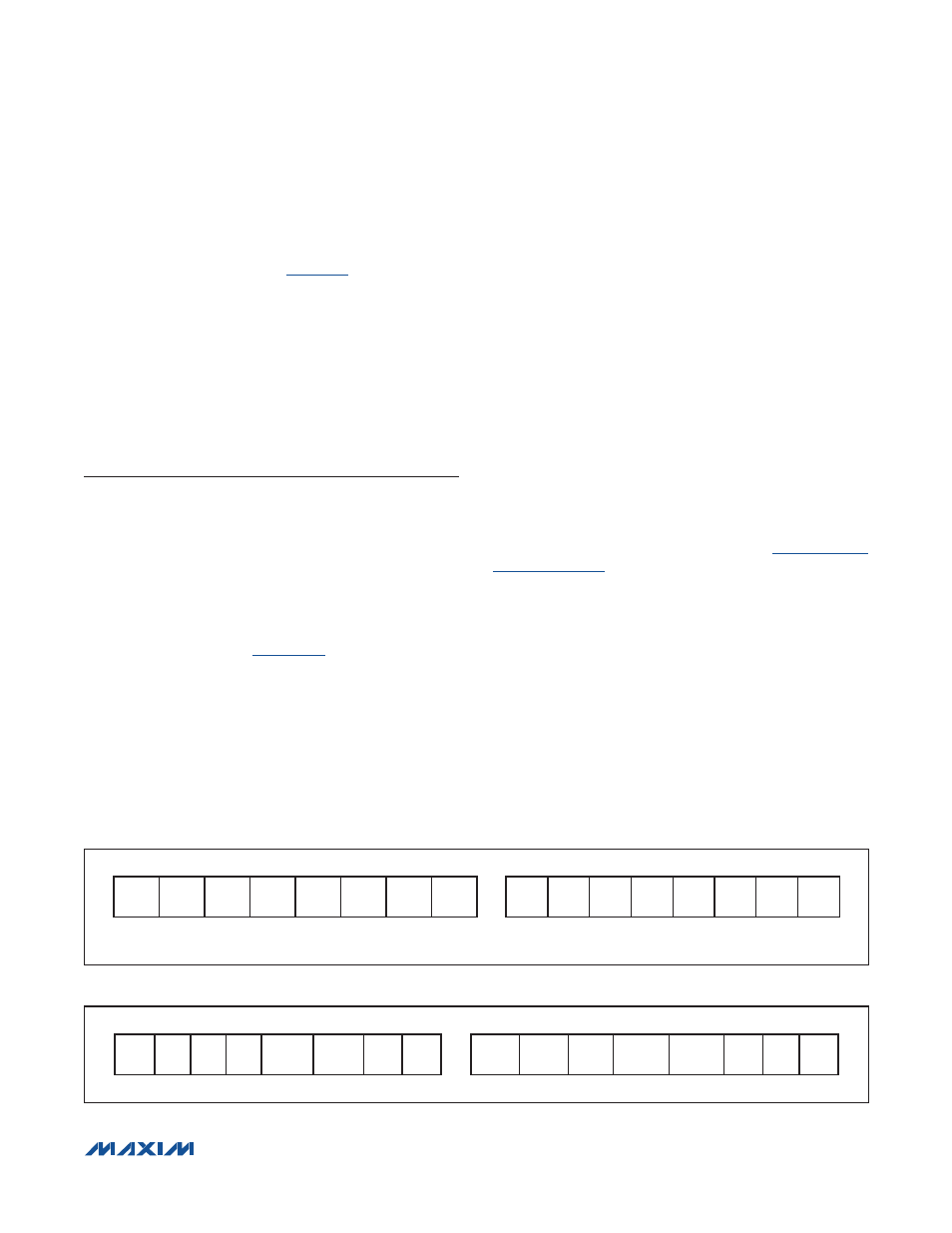
Threshold Register (03h)
The S
ALRT
Threshold register (
) sets upper and
lower limits that generate an ALRT pin interrupt if exceeded
by the selected SOC
REP
, SOC
AV
, SOC
MIX
, or SOC
VF
register values. See the SACFG bits in the MiscCFG
register description for details. The upper 8 bits set the
maximum value and the lower 8 bits set the minimum
value. Interrupt threshold limits are selectable with 1%
resolution over the full operating range of the selected
SOC register. At power-up, the thresholds default to their
maximum settings—FF00h (disabled).
Status and Configuration
The following registers control operation of the ALRT inter-
rupt feature, control transition between active and shut-
down modes of operation, and provide status updates to
the host processor.
CONFIG Register (1Dh)
The CONFIG register holds all shutdown enable, alert
enable, and temperature enable control bits. Writing a
bit location enables the corresponding function within
a 175.8ms task period.
shows the CONFIG
register format.
0—Bit must be written 0. Do not write 1.
Ber—Enable alert on battery removal. When Ber = 1, a
battery-removal condition, as detected by the AIN pin
voltage, triggers an alert. Set to 0 at power-up. Note that
if this bit is set to 1, the ALSH bit should be set to 0 to
prevent an alert condition from causing the device to
enter shutdown mode.
Bei—Enable alert on battery insertion. When Bei = 1, a
battery-insertion condition, as detected by the AIN pin
voltage, triggers an alert. Set to 0 at power-up. Note that
if this bit is set to 1, the ALSH bit should be set to 0 to
prevent an alert condition from causing the device to
enter shutdown mode.
Aen—Enable alert on fuel-gauge outputs. When Aen =
1, violation of any of the alert threshold register values by
temperature, voltage, or SOC triggers an alert. This bit
affects the ALRT pin operation only. The Smx, Smn, Tmx,
Tmn, Vmx, and Vmn bits are not disabled. This bit is set
to 0 at power-up. Note that if this bit is set to 1, the ALSH
bit should be set to 0 to prevent an alert condition from
causing the device to enter shutdown mode.
FTHRM—Force Thermistor Bias Switch. This allows the
host to control the bias of the thermistor switch or enable
fast detection of battery removal (see the
section). Set FTHRM = 1 to always
enable the thermistor bias switch. With a standard 10kI
thermistor, this adds an additional ~200FA to the current
drain of the circuit. This bit is set to 0 at power-up.
ETHRM—Enable Thermistor. Set to logic 1 to enable
the automatic THRM output bias and AIN measurement
every 1.4s. This bit is set to 1 at power-up.
ALSH—ALRT Shutdown. Set to logic 1 and clear the
Aen, Ber, and Bei bits to configure the ALRT pin as an
input to control shutdown mode of the device. The device
enters shutdown if the ALRT pin is held active for longer
than timeout of the SHDNTIMER register. The device
enters active mode immediately on the opposite edge of
the ALRT pin. When set to logic 0, the ALRT pin can func-
tion as an interrupt output. This bit is set to 0 at power-up.
Figure 43. CONFIG Register Format (Input)
Figure 42. S
ALRT
Threshold Register Format (Input)
MSB—ADDRESS 1Dh
LSB—ADDRESS 1Dh
0
S
S
T
S
V
S
ALRTp AINSH Ten
Tex
SHDN I2CSH ALSH ETHRM FTHRM Aen
Bei
Ber
MSb
LSb
MSb
LSb
Figure 42
MSB—ADDRESS 03h
LSB—ADDRESS 03h
MAX
7
MAX
6
MAX
5
MAX
4
MAX
3
MAX
2
MAX
1
MAX
0
MIN
7
MIN
6
MIN
5
MIN
4
MIN
3
MIN
2
MIN
1
MIN
0
MSb
LSb
MSb
LSb
UNITS: 1%