Fstat register (3dh), Atrate register (04h), Figure 34. fstat register format (output – Rainbow Electronics MAX17047 User Manual
Page 26: Figure 35. atrate register format (input
���������������������������������������������������������������� Maxim Integrated Products 26
MAX17047
ModelGauge m3 Fuel Gauge
MR4:MR0—Mixing Rate. This value sets the strength of
the servo mixing rate after the final mixing state has been
reached (> 2.08 complete cycles). The units are MR0 =
6.25FV, giving a range up to 19.375mA with a standard
0.010I sense resistor. Setting this value to 00000b
disables servo mixing and the IC continues with time-
constant mixing indefinitely. The default setting is 25FV
or 2.5mA with a standard sense resistor.
enBi1—Enable reset on battery-insertion detection. Set
this bit to 1 to force a reset of the fuel gauge whenever a
battery insertion is detected based on AIN pin monitoring.
This bit is written to 1 at power-up.
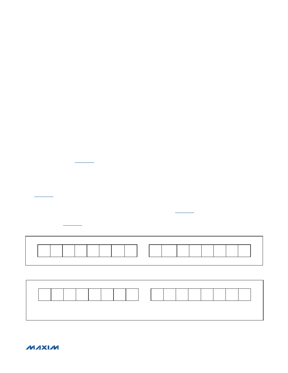
FSTAT Register (3Dh)
The FSTAT register is a read-only register that monitors
the status of the ModelGauge algorithm. Do not write
to this register location.
is the FSTAT register
format:
RelDt—Relaxed cell detection. This bit is set to a 1 when-
ever the ModelGauge m3 algorithm detects that the cell
is in a fully relaxed state. This bit is cleared to 0 whenever
a current greater than the Load threshold is detected.
See
.
RelDt2—Long Relaxation. This bit is set to a 1 whenever
the ModelGauge m3 algorithm detects that the cell has
been relaxed for a period of 48 to 96 minutes or longer.
This bit is cleared to 0 whenever the cell is no longer in a
relaxed state. See
DNR—Data Not Ready. This bit is set to 1 at cell inser-
tion and remains set until the output registers have been
updated. Afterwards, the IC clears this bit indicating the
fuel gauge calculations are now up to date. This takes
between 445ms and 1.845s depending on whether the
IC was in a powered state prior to the cell-insertion event.
EDet—Empty Detection. This bit is set to 1 when the IC
detects that the cell empty point has been reached. This
bit is reset to 0 when the cell voltage rises above the
recovery threshold. See the V_empty register for details.
X—Don’t Care. This bit is undefined and can be logic
0 or 1.
AtRate Register (04h)
The AtRate register allows host software to estimate
remaining capacity, SOC, and time to empty for a theo-
retical load current. Whenever the AtRate register is pro-
grammed to 0 or a positive value, the device uses A/D
measurements for determining the SOC
AV
, RemCap
AV
,
and TTE register values. Whenever the AtRate register is
programmed to a negative value indicating a hypotheti-
cal discharge current, the SOC
AV
, RemCap
AV
, and TTE
registers calculate their values for the AtRate register
theoretical current instead. The AtRate register holds a
two’s-complement 16-bit value. Do not write 8000h to
this register.
shows the AtRate register format.
Figure 34. FSTAT Register Format (Output)
Figure 35. AtRate Register Format (Input)
MSB—ADDRESS 3Dh
LSB—ADDRESS 3Dh
X
X
X
X
X
X
RelDt EDet
X
RelDt2
X
X
X
X
X
DNR
MSb
LSb
MSb
LSb
MSB—ADDRESS 04h
LSB—ADDRESS 04h
S
2
14
2
13
2
12
2
11
2
10
2
9
2
8
2
7
2
6
2
5
2
4
2
3
2
2
2
1
2
0
MSb
LSb
MSb
LSb
2
0
UNITS: 1.5625FV/R
SENSE
X = DON’T CARE