Rainbow Electronics MAX17047 User Manual
Simplified operating circuit, General description, Applications features
MAX17047
ModelGauge m3 Fuel Gauge
����������������������������������������������������������������� Maxim Integrated Products 1
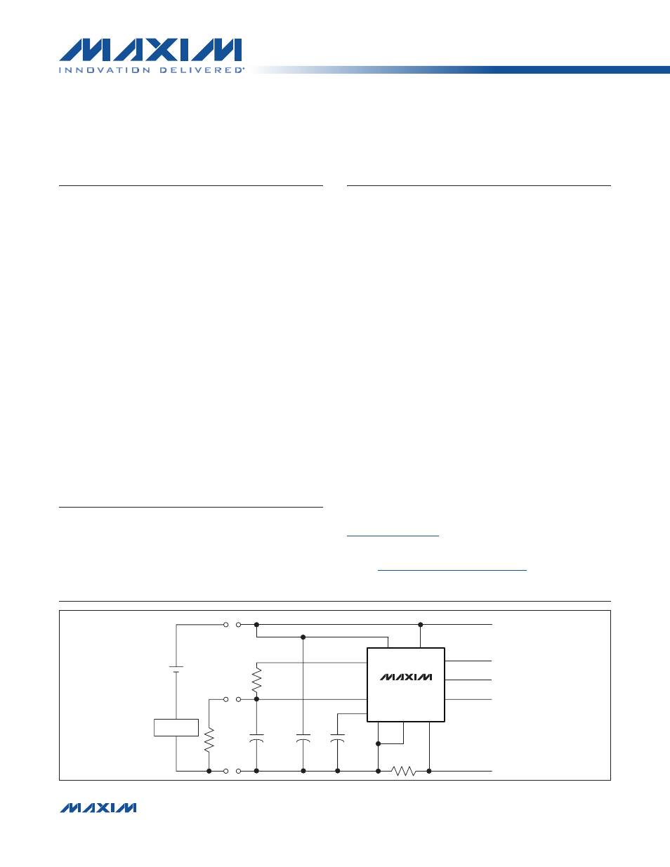
Simplified Operating Circuit
19-6008; Rev 0; 9/11
appears at end of data sheet.
For related parts and recommended products to use with this part,
refer to:
ModelGauge is a trademark of Maxim Integrated Products, Inc.
General Description
The MAX17047 incorporates the Maxim ModelGauge™
m3 algorithm that combines the excellent short-term
accuracy and linearity of a coulomb counter with the
excellent long-term stability of a voltage-based fuel gauge,
along with temperature compensation to provide industry-
leading fuel-gauge accuracy. ModelGauge m3 cancels
offset accumulation error in the coulomb counter, while
providing better short-term accuracy than any purely
voltage-based fuel gauge. Additionally, the ModelGauge
m3 algorithm does not suffer from abrupt corrections that
normally occur in coulomb-counter algorithms, since tiny
continual corrections are distributed over time.
The device automatically compensates for aging, tem-
perature, and discharge rate and provides accurate
state of charge (SOC) in mAh or % over a wide range of
operating conditions. The device provides two methods
for reporting the age of the battery: reduction in capacity
and cycle odometer.
The device provides precision measurements of current,
voltage, and temperature. Temperature of the battery
pack is measured using an external thermistor supported
by ratiometric measurements on an auxiliary input. A
2-wire (I
2
C) interface provides access to data and control
registers. The IC is available in a lead(Pb)-free, 3mm x
3mm, 10-pin TDFN package.
Applications
Features
S
Accurate Battery-Capacity Estimation
Temperature, Age, and Rate Compensated
Does Not Require Empty, Full, or Idle States to
Maintain Accuracy
S
Precision Measurement System
No Calibration Required
S
ModelGauge m3 Algorithm
Long-Term Influence by Voltage Fuel Gauge
Cancels Coulomb-Counter Drift
Short-Term Influence by Coulomb Counter
Provides Excellent Linearity
Adapts to Cell Characteristics
S
External Temperature-Measurement Network
Actively Switched Thermistor Resistive Divider
Reduces Current Consumption
S
Low Quiescent Current
25µA Active, < 0.5µA Shutdown
S
Alert Indicator for SOC, Voltage, Temperature, and
Battery Removal/Insertion Events
S
AtRate Estimation of Remaining Capacity
S
2-Wire (I
2
C) Interface
S
Tiny, Lead(Pb)-Free, 3mm x 3mm, 10-Pin TDFN
Package
2.5G/3G/4G Wireless
Handsets
Smartphones/PDAs
Tablets and Handheld
Computers
Portable Game Players
e-Readers
Digital Still and Video
Cameras
Portable Medical Equipment
0.1µF
0.1µF
OPTIONAL
10nF
OPTIONAL
10k
I
PK-
PK+
T
OPTIONAL
10k
I
NTC
THERMISTOR
10m
I
RSNS
CSP
REG
AIN
SCL
THRM
V
BATT
V
TT
CSN
EP
SDA
ALRT
MAX17047
PROTECTION
SYSTEM
BATTERY PACK
HOST
µP
For pricing, delivery, and ordering information, please contact Maxim Direct at 1-888-629-4642,
or visit Maxim’s website at www.maxim-ic.com.
Document Outline
- General Description
- Applications
- Features
- Simplified Operating Circuit
- Absolute Maximum Ratings
- Electrical Characteristics
- Electrical Characteristics: 2-Wire Interface
- I2C Bus Timing Diagram
- Typical Operating Characteristics
- Typical Operating Characteristics
- Pin Configuration
- Pin Description
- Block Diagram
- Detailed Description
- ModelGauge m3 Algorithm
- Typical Operating Circuit
- Recommended Layout
- ModelGauge m3 Registers
- ModelGauge Algorithm Output Registers
- Application-Specific Registers
- End-of-Charge Detection
- Cell Characterization Information Registers
- Algorithm Configuration Registers
- Power-Up and Power-On Reset
- Battery Removal and Insertion
- Modes of Operation
- ALRT Function
- Status and Configuration
- Voltage Measurement
- Current Measurement
- Temperature Measurement
- IC Memory Map
- 2-Wire Bus System
- Ordering Information
- Package Information
- Revision History
- LIST OF FIGURES
- Figure 1. IC Bus Timing Diagram
- Figure 2. ModelGauge m3 Overview
- Figure 3. ModelGauge m3 OCV and Coulomb-
- Figure 4. ModelGauge m3 Algorithm Mixing
- Figure 5. Typical Operating Circuit
- Figure 6. Operating Circuits that Share
- Figure 7. Proper Board Layout
- Figure 8. ModelGauge m3 Register Map
- Figure 9. SOC Register Format (Output)
- Figure 10. RemCap Register Format (Outpu
- Figure 11. SOC Register Format (Output)
- Figure 12. RemCap Register Format (Outpu
- Figure 13. SOC Register Format (Output)
- Figure 14. RemCap Register Format (Outpu
- Figure 15. SOC Register Format (Output)
- Figure 16. TTE Register Format (Output)
- Figure 17. Age Register Format (Output)
- Figure 18. Cycles Register Format (Outpu
- Figure 19. VFOCV Register Format (Output
- Figure 20. FullCAP Register Format (Outp
- Figure 21. FullCapNom Register Format (O
- Figure 22. QH Register Format (Output)
- Figure 23. DesignCap Register Format (In
- Figure 24. FullSOCThr Register Format (I
- Figure 25. False End-of-Charge Events
- Figure 26. FullCAP Learning at End of Ch
- Figure 27. ICHGTerm Register Format (Inp
- Figure 28. V_empty Register Format (Inpu
- Figure 29. FilterCFG Register Format (In
- Figure 30. RelaxCFG Register Format (Inp
- Figure 31. Cell Relaxation Detection
- Figure 32. LearnCFG Register Format (Inp
- Figure 33. MiscCFG Register Format (Inpu
- Figure 34. FSTAT Register Format (Output
- Figure 35. AtRate Register Format (Input
- Figure 37. Operation After Cell Insertio
- Figure 38. Fast Detection of Cell Remova
- Figure 39. MAX17047 State Based on Shutd
- Figure 40. V Threshold Register Format (
- Figure 41. T Threshold Register Format (
- Figure 42. S Threshold Register Format (
- Figure 43. CONFIG Register Format (Input
- Figure 44. Timer Register Format (Output
- Figure 45. SHDNTIMER Register Format (In
- Figure 46. Status Register Format (Input
- Figure 47. Version Register Format (Outp
- Figure 48. V Register Format (Output)
- Figure 49. AverageV Register Format (Out
- Figure 50. MaxMinV Register Format (Outp
- Figure 51. Current Register Format (Outp
- Figure 52. AverageCurrent Register Forma
- Figure 53. MaxMinCurrent Register Format
- Figure 54. CGAIN Register Format (Input)
- Figure 55. COFF Register Format (Input)
- Figure 56. AIN Register Format (Output)
- Figure 57. Temperature Register Format (
- Figure 58. AverageTemperature Register F
- Figure 59. MaxMinTemperature Register Fo
- Figure 60. TGAIN Register Format (Input)
- Figure 61. TOFF Register Format (Input)
- LIST OF TABLES