Block diagram, Detailed description, Modelgauge m3 algorithm – Rainbow Electronics MAX17047 User Manual
Page 8: Block diagram detailed description
����������������������������������������������������������������� Maxim Integrated Products 8
MAX17047
ModelGauge m3 Fuel Gauge
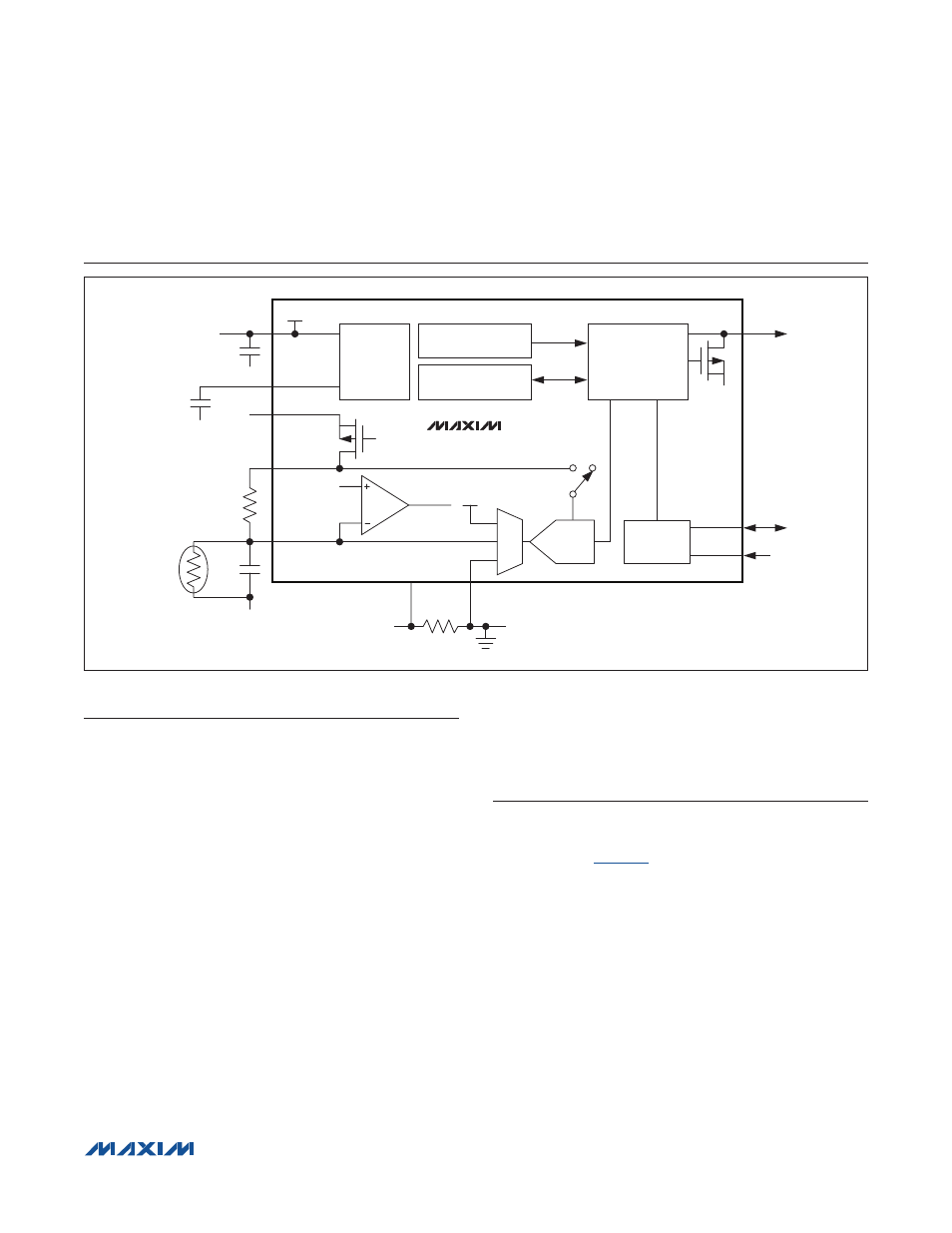
Block Diagram
Detailed Description
The MAX17047 incorporates the Maxim ModelGauge m3
algorithm that combines the excellent short-term accu-
racy and linearity of a coulomb counter with the excellent
long-term stability of a voltage-based fuel gauge, along
with temperature compensation to provide industry-
leading fuel-gauge accuracy. ModelGauge m3 cancels
offset accumulation error in the coulomb counter, while
providing better short-term accuracy than any purely
voltage-based fuel gauge. Additionally, the ModelGauge
m3 algorithm does not suffer from abrupt corrections that
normally occur in coulomb-counter algorithms, since tiny
continual corrections are distributed over time.
The device automatically compensates for aging, tem-
perature, and discharge rate and provides accurate SOC
in mAh or % over a wide range of operating conditions.
The device provides two methods for reporting the age
of the battery: reduction in capacity and cycle odometer.
The device provides precision measurements of current,
voltage, and temperature. Temperature of the battery
pack is measured using an external thermistor supported
by ratiometric measurements on an auxiliary input. A
2-wire (I
2
C) interface provides access to data and control
registers. The device is available in a 3mm x 3mm, 10-pin
TDFN package.
ModelGauge m3 Algorithm
The ModelGauge m3 algorithm combines a high-accura-
cy coulomb counter with a voltage fuel gauge (VFG) as
represented in
.
Classical coulomb-counter-based fuel gauges have
excellent linearity and short-term performance. However,
they suffer from drift due to the accumulation of the offset
error in the current-sense measurement. Although the
offset error is often very small, it cannot be eliminated,
causes the reported capacity error to increase over
time, and requires periodic corrections. Corrections are
usually performed at full or empty. Some other systems
also use the relaxed battery voltage to perform correc-
tions. These systems determine the SOC based on the
battery voltage after a long time of no current flow. Both
have the same limitation: if the correction condition is not
observed over time in the actual application, the error in
0.1µF
PK-
PK-
CSP
PK-
PK-
SYSTEM GROUND
PK+
PK+
10nF
0.1µF
10m
I
RSNS
32kHz OSCILLATOR
OCV CALCULATION
ModelGauge m3
ALGORITHM
2V LDO
V
BATT
V
BATT
REG
P
SDA
ALRT
SCL
V
TT
THRM
V
THRM
- V
DETR
/V
DETF
BATTERY
REMOVAL
REF
DETECT
CSP
CSN
AIN
IN
OUT
MUX
12-BIT ADC
I
2
C
INTERFACE
REF ADC
MAX17047