Tgain register 2ch/toff register (2dh), Ic memory map, Figure 58. averagetemperature register f – Rainbow Electronics MAX17047 User Manual
Page 40: Figure 59. maxmintemperature register fo, Figure 60. tgain register format (input), Figure 58
���������������������������������������������������������������� Maxim Integrated Products 40
MAX17047
ModelGauge m3 Fuel Gauge
the maximum or less than the minimum, the correspond-
ing values are replaced with the new reading. At power-
up, the MaxTemperature value is set to 80h (minimum)
and the MinTemperature value is set to 7Fh (maximum).
Therefore, both values are changed to the Temperature
register reading after the first update. Host software can
reset this register by writing it to its power-up value of
807Fh. The maximum and minimum temperatures are
each stored as two’s complement 8-bit values with 1NC
resolution.
register format.
TGAIN Register (2Ch)/TOFF Register (2Dh)
The TGAIN and TOFF registers adjust the gain and offset
of the temperature measurement A/D on the AIN pin to
convert the result to a temperature value by the following
equation:
Temperature Register = (AIN Register O
TGAIN Register/16384) + (TOFF Register O 2)
Both these registers are signed two’s complement. These
registers allow for accurate temperature conversions when
using a variety of external NTC thermistors (see
).
shows the TGAIN register format and
shows the TOFF register format.
IC Memory Map
The device has a 256-word linear memory space con-
taining all user-accessible registers. All registers are
16 bits wide and are read and written as 2-byte values.
When the MSB of a register is read, the MSB and LSB
are latched simultaneously and held for the duration of
the Read Data command. This prevents updates to the
LSB during the read, ensuring synchronization between
the 2 register bytes.
All locations are volatile RAM and lose their data in the
event of power loss. Data is retained during device
shutdown. Each register has a power-on-reset value that
it defaults to at power-up. Word addresses designated
as reserved return an undetermined when read. These
locations should not be written.
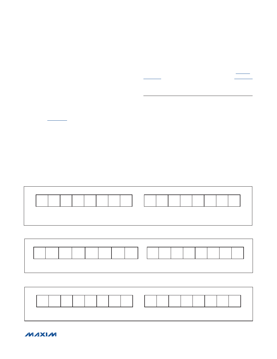
Figure 60. TGAIN Register Format (Input)
Figure 58. AverageTemperature Register Format (Output)
Figure 59. MaxMinTemperature Register Format (Output)
Figure 60
MSB—ADDRESS 2Ch
LSB—ADDRESS 2Ch
S
2
14
2
13
2
12
2
11
2
10
2
9
2
8
2
7
2
6
2
5
2
4
2
3
2
2
2
1
2
0
MSb
LSb
MSb
LSb
2
0
UNITS: +1NC/64
Figure 58
MSB—ADDRESS 16h
LSB—ADDRESS 16h
S
2
6
2
5
2
4
2
3
2
2
2
1
2
0
2
-1
2
-2
2
-3
2
-4
2
-5
2
-6
2
-7
2
-8
MSb
LSb
MSb
LSb
2
-8
UNITS: +0.0039NC
2
0
UNITS: +1.0NC
Figure 59
MSB—ADDRESS 1Ah
LSB—ADDRESS 1Ah
S
MAX
6
MAX
5
MAX
4
MAX
3
MAX
2
MAX
1
MAX
0
S
MIN
6
MIN
5
MIN
4
MIN
3
MIN
2
MIN
1
MIN
0
MSb
LSb
MSb
LSb
UNITS: +1NC