Alrt function, Valrt threshold register (01h), Talrt threshold register (02h) – Rainbow Electronics MAX17047 User Manual
Page 31: Figure 40. v threshold register format, Figure 41. t threshold register format
���������������������������������������������������������������� Maxim Integrated Products 31
MAX17047
ModelGauge m3 Fuel Gauge
ALRT Function
The Alert Threshold registers allow interrupts to be
generated by detecting a high or low voltage, a high or
low temperature, or a high or low SOC. Interrupts are
generated on the ALRT pin open-drain output driver. An
external pullup is required to generate a logic-high sig-
nal. Note that if the pin is configured to be logic-low when
inactive, the external pullup increases current drain.
The ALRTp bit in the CONFIG register sets the polarity of
the ALRT pin output. Alerts can be triggered by any of the
following conditions:
• Battery removal—(V
AIN
> V
THRM
- V
DETR
) and bat-
tery removal detection enabled (Ber = 1).
• Battery insertion—(V
AIN
< V
THRM
- V
DETF
) and bat-
tery insertion detection enabled (Bei = 1).
• Over-/undervoltage—V
ALRT
threshold violation
(upper or lower) and alerts enabled (Aen = 1).
• Over-/undertemperature—T
ALRT
threshold violation
(upper or lower) and alerts enabled (Aen = 1).
• Over/under SOC—S
ALRT
threshold violation (upper
or lower) and alerts enabled (Aen = 1).
To prevent false interrupts, the threshold registers should
be initialized before setting the Aen bit. Alerts generated by
battery insertion or removal can only be reset by clearing
the corresponding bit in the Status register. Alerts gener-
ated by a threshold-level violation can be configured to
be cleared only by software, or cleared automatically
when the threshold level is no longer violated. See the
CONFIG (1Dh) register description for details of the alert
function configuration.
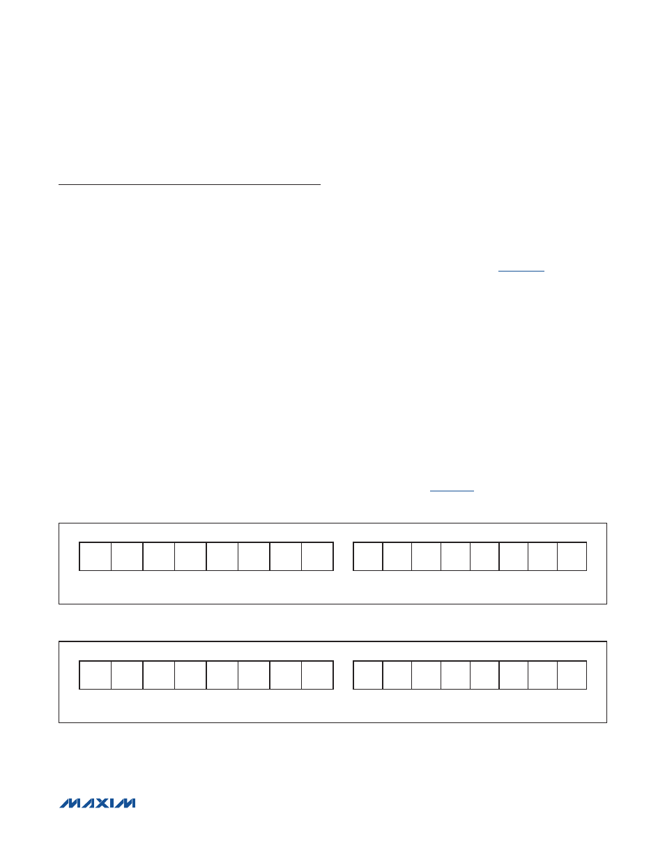
V
ALRT
Threshold Register (01h)
The V
ALRT
Threshold register (
) sets upper
and lower limits that generate an ALRT pin interrupt if
exceeded by the V
CELL
register value. The upper 8
bits set the maximum value and the lower 8 bits set the
minimum value. Interrupt threshold limits are selectable
with 20mV resolution over the full operating range of the
V
CELL
register. At power-up, the thresholds default to
their maximum settings—FF00h (disabled).
T
ALRT
Threshold Register (02h)
The T
ALRT
Threshold register sets upper and lower limits
that generate an ALRT pin interrupt if exceeded by the
Temperature register value. The upper 8 bits set the max-
imum value and the lower 8 bits set the minimum value.
Interrupt threshold limits are stored in two’s-complement
format and are selectable with 1NC resolution over the full
operating range of the Temperature register. At power-
up, the thresholds default to their maximum settings—
7F80h (disabled).
shows the T
ALRT
Threshold
register format.
Figure 40. V
ALRT
Threshold Register Format (Input)
Figure 41. T
ALRT
Threshold Register Format (Input)
Figure 40
MSB—ADDRESS 01h
LSB—ADDRESS 01h
MAX
7
MAX
6
MAX
5
MAX
4
MAX
3
MAX
2
MAX
1
MAX
0
MIN
7
MIN
6
MIN
5
MIN
4
MIN
3
MIN
2
MIN
1
MIN
0
MSb
LSb
MSb
LSb
UNITS: 20mV
Figure 41
MSB—ADDRESS 02h
LSB—ADDRESS 02h
S
MAX
6
MAX
5
MAX
4
MAX
3
MAX
2
MAX
1
MAX
0
S
MIN
6
MIN
5
MIN
4
MIN
3
MIN
2
MIN
1
MIN
0
MSb
LSb
MSb
LSb
UNITS: 1NC