3 pca interrupt, 4 pca capture mode – Rainbow Electronics T89C51AC2 User Manual
Page 71
71
T89C51AC2
Rev. B – 19-Dec-01
Each module in the PCA has a special function register associated with it (CCAPM0 for
module 0 ...). The CCAPM0:4 registers contain the bits that control the mode that each
module will operate in.
•
The ECCF bit enables the CCF flag in the CCON register to generate an interrupt
when a match or compare occurs in the associated module.
•
The PWM bit enables the pulse width modulation mode.
•
The TOG bit when set causes the CEX output associated with the module to toggle
when there is a match between the PCA counter and the module’s capture/compare
register.
•
The match bit MAT when set will cause the CCFn bit in the CCON register to be set
when there is a match between the PCA counter and the module’s capture/compare
register.
•
The two bits CAPN and CAPP in CCAPMn register determine the edge that a
capture input will be active on. The CAPN bit enables the negative edge, and the
CAPP bit enables the positive edge. If both bits are set both edges will be enabled.
•
The bit ECOM in CCAPM register when set enables the comparator function.
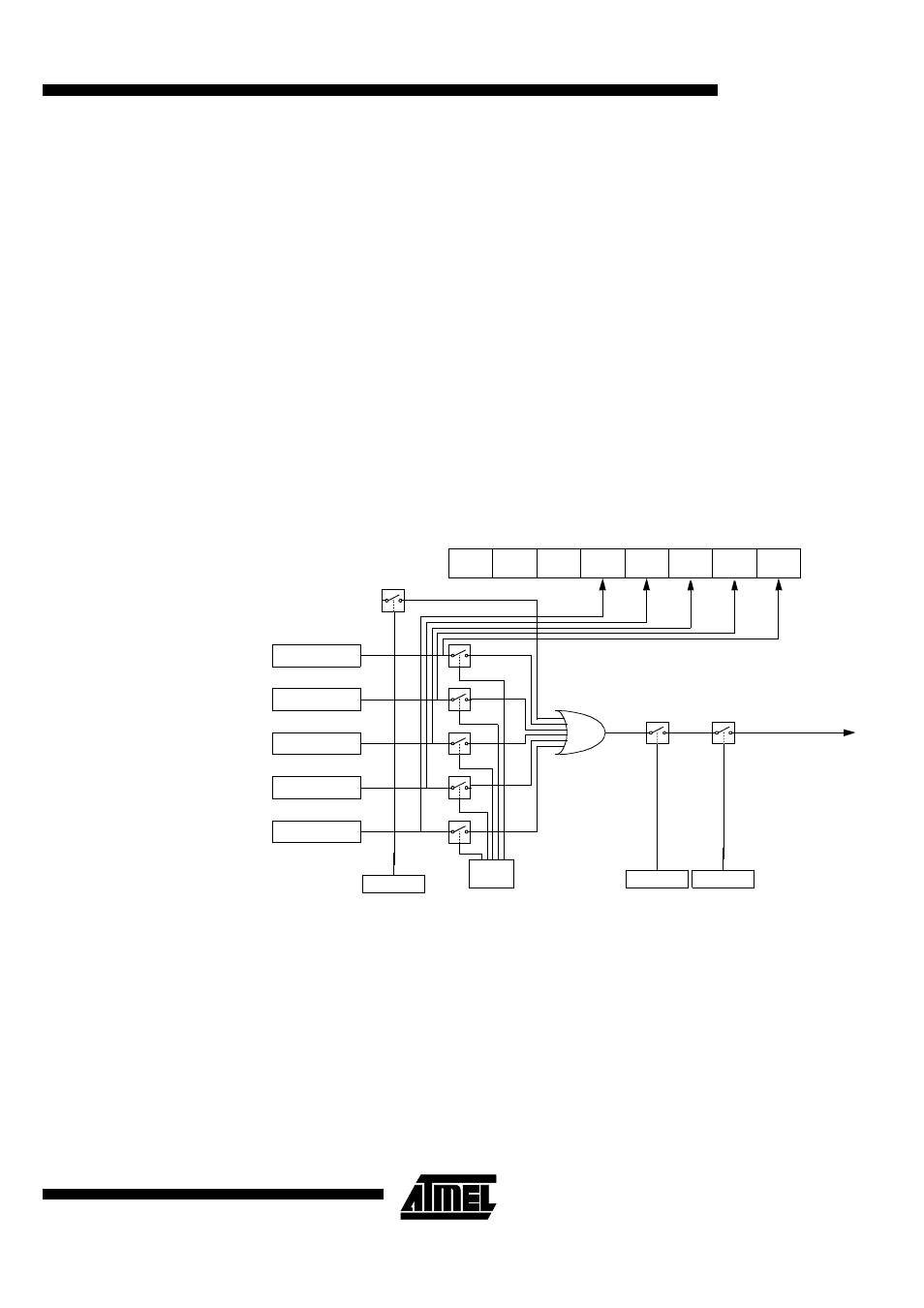
15.3 PCA Interrupt
Figure 31. PCA Interrupt System
15.4 PCA Capture Mode
To use one of the PCA modules in capture mode either one or both of the CCAPM bits
CAPN and CAPP for that module must be set. The external CEX input for the module
(on port 1) is sampled for a transition. When a valid transition occurs the PCA hardware
loads the value of the PCA counter registers (CH and CL) into the module’s capture reg-
isters (CCAPnL and CCAPnH). If the CCFn bit for the module in the CCON SFR and the
ECCFn bit in the CCAPMn SFR are set then an interrupt will be generated.
CF
CR
CCON
CCF4 CCF3
CCF2
CCF1
CCF0
Module 4
Module 3
Module 2
Module 1
Module 0
PCA Timer/Counter
ECCFn
CCAPMn.0
To Interrupt
EA
IEN0.7
EC
IEN0.6
ECF
CMOD.0