Figure 22 – Rainbow Electronics T89C51AC2 User Manual
Page 52
52
T89C51AC2
Rev. B – 19-Dec-01
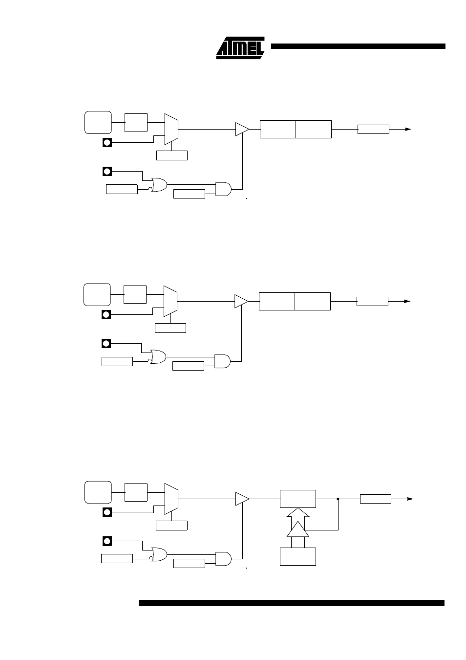
Figure 22. Timer/Counter x (x= 0 or 1) in Mode 0
12.2.2 Mode 1 (16-bit Timer)
Mode 1 configures Timer 0 as a 16-bit Timer with TH0 and TL0 registers connected in
cascade (see Figure 23). The selected input increments TL0 register.
Figure 23. Timer/Counter x (x= 0 or 1) in Mode 1
12.2.3 Mode 2 (8-bit Timer with
Auto-Reload)
Mode 2 configures Timer 0 as an 8-bit Timer (TL0 register) that automatically reloads
from TH0 register (see Figure 24). TL0 overflow sets TF0 flag in TCON register and
reloads TL0 with the contents of TH0, which is preset by software. When the interrupt
request is serviced, hardware clears TF0. The reload leaves TH0 unchanged. The next
reload value may be changed at any time by writing it to TH0 register.
Figure 24. Timer/Counter x (x= 0 or 1) in Mode 2
FTx
CLOCK
TRx
TCON reg
TFx
TCON reg
0
1
GATEx
TMOD reg
÷
6
Overflow
Timer x
Interrupt
Request
C/Tx#
TMOD reg
TLx
(5 bits)
THx
(8 bits)
INTx#
Tx
see section “Clock”
TRx
TCON reg
TFx
TCON reg
0
1
GATEx
TMOD reg
Overflow
Timer x
Interrupt
Request
C/Tx#
TMOD reg
TLx
(8 bits)
THx
(8 bits)
INTx#
Tx
FTx
CLOCK
÷
6
see section “Clock”
TRx
TCON reg
TFx
TCON reg
0
1
GATEx
TMOD reg
Overflow
Timer x
Interrupt
Request
C/Tx#
TMOD reg
TLx
(8 bits)
THx
(8 bits)
INTx#
Tx
FTx
CLOCK
÷
6
see section “Clock”